Table of Contents
Advertisement
Advertisement
Table of Contents

Related Manuals for CIAT FLOWAY CLASSIC PHE


Summarization of Contents
2 - REGULATING CONTROLLER
2.1 Introduction
Overview of the control PLC's functions and connectivity for monitoring and controlling the air handling unit.
2.2 Inputs/outputs
Description of the PLC's analogue and on/off inputs/outputs and their designations.
2.3 Alphanumeric terminal
Details about the alphanumeric terminal, its connection, usage, and screen symbols.
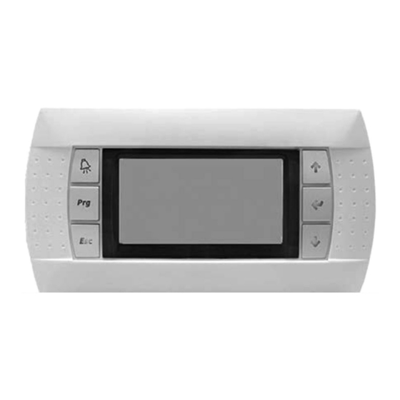
2.4 Touchscreen terminal
Information on the touchscreen terminal, its connection, usage, and menu navigation.
3 - FEATURES
3.1 Management of on and off modes
How to start and stop the unit via terminal or CMS, including remote control and frost protection.
3.2 Managing setpoints
Explanation of setpoint management for temperatures and flow rates, and parameter usage.
3.3 Safety and isolation damper
Information on the safety and isolation dampers, their activation, and opening time delay.
3.4 Mixing damper
Configuration and operation of the mixing damper, including opening time and minimum setpoints.
3.5 Filter management
How pressure sensors measure filter fouling and trigger faults, and filter type configuration.
3.6 Temperature control
How temperature is controlled, including setpoint selection, PID calculation, and priority of heating/cooling elements.
3.7 Fan control
Details on EC motor fans, flow rate control, and pressure control settings.
3.8 Energy recovery
Operation of rotary or plate heat exchangers, conditions for energy recovery, and defrost monitoring.
3.9 Coils
Information on hydraulic/electric coils, mixed coil scenarios, and frost protection.
3.10 Free Cooling
How free cooling works, conditions for activation, and temperature limits.
3.11 Night cooling
How night cooling is activated, conditions, and fan control based on flow rate.
3.12 CO2 air quality
Activating air quality function, CO2 sensor connection, and control based on IAQ requirement.
3.13 Fire protection
How fire detection is activated, operating modes in case of fire, and safety strategies.
3.14 Remote control in Th-Tune room
Details on the optional room thermostat, its functions, connection, and status symbols.
3.15 Temperature setpoint compensation
How temperature setpoints are adjusted based on outdoor temperature using compensation curves.
3.16 Downgraded fresh air flow rate
Function to limit fresh air flow rate based on outdoor temperature for fan control.
3.17 Time management
Setting date and time for programming and fault recording, and battery backup.
3.18 Time schedule
Changing unit operating mode based on time, day, or season using weekly/annual programs.
3.19 Access level
Explanation of the three access levels (customer, installer, manufacturer) for parameter modification.
4 - MANAGING THE CONNECTION BETWEEN CONTROLLERS AND ALPHANUMERIC TERMINALS
4.1 One controller and one LCD terminal
Procedure for connecting one controller with one LCD terminal and addressing.
4.2 Several controllers and terminals
How multiple controllers and terminals can be interconnected using the pLAN (local area network).
4.3.1 Connecting controllers to the pLAN
Details on connecting controllers using shielded cable via RS485 for the pLAN network.
4.3.2 Connecting a remote screen to the pLAN
How to connect a user terminal to the pLAN network, including distance considerations.
4.4.1 Operation
Explanation of the addressing system for controllers and terminals on the pLAN network.
4.4.2 Modifying the HMI LCD terminal addresses
Procedure for changing the address of the HMI LCD terminal connected to the controller.
4.4.3 Modifying the controller addresses
How to modify the controller's pLAN address, directly from the controller itself.
4.4.4 Allocating private and shared HMI terminals
Process for defining terminal lists for each controller, distinguishing between private and shared terminals.
4.4.5 Checking the pLAN address
How to display and verify the pLAN addresses of controllers and terminals, and troubleshoot connection issues.
4.4.6 Accessing the various controllers on a network from a shared HMI terminal
Method for switching between controllers when using a shared HMI terminal on the network.
5 - CONNECTION TO A CMS
5.1 Modbus RTU
Configuration for Modbus RTU communication protocol between the controller and BMS.
5.2 Modbus TCP/IP and BACnet IP
Steps for configuring Modbus TCP/IP and BACnet IP communication with the unit controller.
5.3 LON
Requirements and process for connecting the unit to a LON network using specific boards and software.
5.4 KNX
How to connect the unit to a KNX network, including board installation, bus configuration, and database creation.
6 - COMMISSIONING
6.1 Actions required prior to commissioning
Necessary checks and procedures before performing the unit's commissioning.
6.2 Test mode
How to use test mode to individually test PLC outputs and the implications of its use.
6.3 Calibration
Procedure for calibrating various sensors, including temperature and pressure sensors, and offset adjustments.
7 - FAULTS
7.1 Type of faults
Classification of faults into "maintenance" and "danger" types and their implications.
7.2 Fault relays
Information on the PLC's maintenance and danger fault summary relays.
7.3 Fault memory
How the PLC stores the last 100 faults with date and time, noting it cannot be cleared.
7.4 List of faults
A comprehensive list of detected faults, their designation, and fault level (maintenance/danger).
7.5 Diagnostics
A table detailing faults, their sources, causes, and suggested solutions for troubleshooting.
8 - PARAMETERS
8.1 Machine parameters
List of machine parameters, their settings, default values, and access levels for configuration.
8.2 Setting parameter
Detailed list of settable parameters, including language, date/time, fan controls, and PID settings.
8.3 Reading parameter
List of parameters available for reading, showing their current values and associated conditions.
8.4 Versions
Information on different software and hardware versions of the AHU.
8.5 Fault level
Parameters related to fault levels, categorizing them as maintenance or danger.
8.6 Communication parameters
Settings for communication protocols (BMS1, BMS2, pLAN) including address, speed, and parity.
8.7 Calibration
Procedures for calibrating various sensors like flow rate, pressure, and temperature sensors.
8.8 SW direction
Configuration of input/output directions for various functions like remote control, fire detection, and pump checks.
8.9 Prioritisation
Parameters defining the priority of different operating modes like cooling, heating, and electric heater stages.
8.10 Intake FMA EC motor
Parameters specific to the intake FMA EC motor, such as min/max speed percentage.
8.11 Exhaust FMA EC motor
Parameters specific to the exhaust FMA EC motor, such as min/max speed percentage.
Need help?
Do you have a question about the FLOWAY CLASSIC PHE and is the answer not in the manual?
Questions and answers