Table of Contents
Advertisement
Quick Links
Advertisement
Table of Contents

Related Manuals for CIAT COMFORT LINE


Summary of Contents for CIAT COMFORT LINE
- Page 1 EN7533229-03 06 - 2022 I n s t r u c t i o n m a n u a l...
- Page 2 COLIS PACKAGE +50°C COLIS / PACKAGE 35 kg COLIS PACKAGE -10°C COMFORT LINE...
- Page 3 Fig. 1 COMFORT LINE...
- Page 4 P. moteur/Motor P. (W) Elec Element (Ph/Hz/V) Maxi pressure 74/89 1+N 50/60HZ230/220V 1600000 PA (16BAR) I. moteur/Motor I. (A) Elec Element P. (W)/I.(A) Cablage/Wiring 0.32/0.38 tr. mn - 1/r.p.m. Elec Diagram N° Declaration CE 7349014 7341384.00 Fig. 3 COMFORT LINE...
- Page 5 Fig. 4 Fig. 5 COMFORT LINE...
- Page 6 Fig. 6 Fig. 7 Fig. 8 COMFORT LINE...
- Page 7 Fig. 9 Fig. 10 COMFORT LINE...
- Page 8 Fig. 11 Fig. 12 COMFORT LINE VIII...
- Page 9 Fig. 13 COMFORT LINE...
- Page 10 Fig. 14 COMFORT LINE...
- Page 11 Fig. 15 COMFORT LINE...
- Page 12 Fig. 16 Fig. 17 COMFORT LINE...
- Page 13 Fig. 18 XIII COMFORT LINE...
- Page 14 Fig. 19 T6 : 590 1313 T0 : 538, T1 T5 : 649 T6 : 420 T6 : 368 T0 : 131 T1 <-> T6 : 192 Poids/Weight/Gewicht/Peso/Peso/Gewicht/Вес/ağırlık COMFORT LINE 15,5 COMFORT LINE...
-
Page 15: Table Of Contents
5.2 - Condensate drain pan ..........................27 5.3 - Fan motor assembly ............................28 5.4 - Heat exchange coil ............................29 6 - CERTIFICATE OF CONFORMITY ........................30 7 - TESTING & WARRANTY ..........................30 8 - SAFETY CONSIDERATIONS RELATING TO FINAL SHUT-DOWN ..............31 EN-15 COMFORT LINE... -
Page 16: Unpacking, Checking And Storing The Unit
1 - UNPACKING, CHECKING AND STORING THE UNIT Thank you for purchasing a CIAT unit. We trust that this unit will give you complete satisfaction. To ensure correct operation, all connections (electrical, hydraulic, etc.) must be made in accordance with best industry practice and the regulations in force in the country of installation. -
Page 17: Handling
It is possible to carry out the installation using a fork-lift truck, as long as care is taken not to damage the unit. The unit is placed inside the suspended ceiling. If the return has no duct, ensure that the rear of the unit is at a sufficient distance from the wall (X = min. 250 mm). EN-17 COMFORT LINE... -
Page 18: Description Of The Unit (Fig. 1)
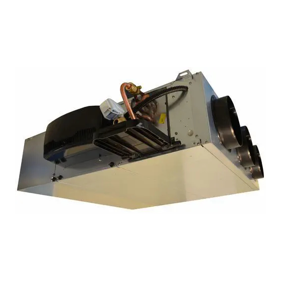
3 - DESCRIPTION OF THE UNIT (FIG. 1) The COMFORT LINE™ (CFL) unit that you have just purchased is part of a range of comfort units with high available static pressure. It is used for heating, cooling, dehumidification and air filtration. It includes a coil with one or two hot water or cold water supply circuits and may include an electrical heater for heating. -
Page 19: Models
3 - DESCRIPTION OF THE UNIT (FIG. 1) 3.2 - Models The COMFORT LINE is available in 8 standard models: I : Metal sleeve on the discharge (optional on size 0) LI : Air recovery grille integrated into the device, with air... -
Page 20: Nstallation And Connections
(optional, fig.3, a) or a nut/washer assembly positioned filter bypass problems. on either side of the mounting bracket (fig.3, b). Note: CIAT strongly recommends the use of anti- 4.2.3 - Adjusting the fresh air collars (Fig.4): vibration resilient mounts when securing the unit, in order to reduce the transmission of vibrations Either remove or leave on the shims needed to obtain through the building structure during operation. - Page 21 ] < 30 mg/l 4.3.1 - Installation ■ Resistivity 2000 < Resistivity < 5000 Ωcm To avoid damaging the CIAT valves or couplings, never ■ pH 6,9 < pH < 8 torque tighten to more than 3,5 daN.m. Use two wrenches, one to hold and the other to tighten, to ensure 4.3.7 - Operating limit recommendations:...
-
Page 22: Condensate Pump Draining Connection
50°C. This is especially important for units installed in confined spaces (e.g. in suspended ceilings). CIAT shall not be liable for damage to valves caused by faulty design of the hydraulic supply network or incorrect commissioning. To protect against the risk of condensation when using chilled water, lagging should be placed along the entire lengths of pipes and the ends must be completely sealed. - Page 23 Make sure that the flow of water to be discharged in the thermal selection is suitable for your application. Note: this accessory must always be used with a valve control device, to ensure valve control of the high safety device when the valve is closed (closure of the condensate drains). EN-23 COMFORT LINE...
-
Page 24: Electrical Connections
Beware of the risk of burns. Only personnel qualified to work on electrical connections may carry out installation and maintenance work. Before connecting the unit to the network, ensure that the voltage matches that indicated on the name plate (230 ±10%/1- ph/50-60 Hz). AC Asynchronous Motor HEE Brushless Motor Motor COMFORT LINE reference Max power input 0,31 0,32 0,53 0,70 0,77 0,95 2,68 0,37 0,25 0,47... - Page 25 4 - NSTALLATION AND CONNECTIONS An earth connection is compulsory. CIAT shall not be liable for incidents resulting from faulty or non- existent earthing. Always follow the wiring diagram delivered with unit. To access the electrical terminal block: Disconnect the unit from the electrical power supply Use a Phillips screwdriver or a size 7 Allen key to undo the 2 screws securing the electrics box cover (Fig.10).
- Page 26 For size 0, if the thermo fuse is blown, then the electrical heater must be replaced. ■ Remove the fan motor assembly (see the section "Removing the fan motor assembly"). ■ Disconnect the faston terminals which make up the electrical heater's wiring loom from the heater. ■ Undo the screws on the electrical heater (Fig.12, d). Perform these steps in reverse to fit the new electrical heater. For sizes 1 to 6, the unit can be manually reset by inserting a screwdriver in the hole (fig.12, e). COMFORT LINE EN-26...
-
Page 27: Servicing And Maintenance
2 lugs sharply upwards. The above recommendations are for information only. - Check that the grille is securely affixed. CIAT recommends regular inspections of the filter's appearance in order to define the frequency with which 5.2 - Condensate drain pan it should be replaced, which varies depending on the premises and the operating conditions. -
Page 28: Fan Motor Assembly
- Remove the removable lower panel (a) using the - Lower the FMA and release it from the central lock 4 screws. hole. - Remove the removable panel. For size 0, ensure the filter is guided downwards as the only support is provided by the removable panel. COMFORT LINE EN-28... -
Page 29: Heat Exchange Coil
For sizes 1 to 6, refer to the section "Removing the holes. condensate drain pans". To refit, perform the operation in reverse order. To refit, perform the operation in reverse order, remembering to bleed the coil before refilling with water. CIAT's products carry the CE mark, demonstrating that they may be sold throughout the European Union. This mark is your assurance that CIAT's products are safe to use. EN-29 COMFORT LINE... -
Page 30: Certificate Of Conformity
■ Toshiba Carrier UK Ltd, Porsham Close, Roborough, Plymouth, PL6 7DB 7 - TESTING & WARRANTY All our units are tested and proven before leaving the factory. They are guaranteed against all manufacturing defects. CIAT shall not be held liable for any type of corrosion. CIAT's warranty does not cover damage resulting from incorrect electrical wiring, inadequate electrical or thermal protection or failure to use a filter. -
Page 31: Safety Considerations Relating To Final Shut-Down
Sort the components according to their material for recycling or disposal, in accordance with regulations in force. Materials to be recovered for recycling - Steel - Copper - Brass - Aluminium - Plastics - Insulation. The proportions of materials for each unit are listed in the Product Environmental Profile (PEP) available at the following website: http://www.pep-ecopassport.org/fr/consulter-les-pep/ or on request from our departments. Any contaminated fluids must be disposed of by specialist professionals. EN-31 COMFORT LINE... - Page 32 Manufacturer: Carrier S.C.S, Rte de Thil - 01120 Montluel, France. Printed in the European Union. Manufacturer reserves the right to change any product specifications without notice.
Need help?
Do you have a question about the COMFORT LINE and is the answer not in the manual?
Questions and answers