Table of Contents
Advertisement
Advertisement
Table of Contents

Related Manuals for CIAT AirCompact Control


Summary of Contents for CIAT AirCompact Control
- Page 1 NA 13.12 B 03 – 2015 C ontrol manual...
-
Page 2: Table Of Contents
CONTENTS Supervision and control ........................4 The program..............................4 The HMI terminal ............................4 1.2.1 Using the HMI terminal keys ..........................5 The room terminal (Option) ........................6 1.3.1 Controls ..................................6 1.3.2 Displays ..................................7 1.3.3 Room terminal information, settings and browsing ..................... 8 1.3.4 Managing alarms.............................. - Page 3 Versions menu ............................. 35 Time schedule menu ..........................35 Communication menu ..........................37 2.10 Alarms menu ............................. 37 2.11 Test mode menu ............................37 2.12 Access level menu ..........................39 2.13 Master/Slave menu ..........................40 Managing a network of controllers ....................40 pLAN electrical connections ........................
-
Page 4: Supervision And Control
Supervision and control The program This air handling unit is managed by its controller. In addition to its control functions, it also monitors and detects any faults with the air handling unit. The HMI terminal displays the following data which can be edited at any time: . -
Page 5: Using The Hmi Terminal Keys
1.2.1 Using the HMI terminal keys Description Returns to the main Menu mask when pressed in any loop. The Menu loop displays the state of the unit. Provides access to the "Menu" Resets all setpoints, parameters and time delay values to their factory settings. The red button is used to display alarms and confirm acknowledgeable faults. -
Page 6: The Room Terminal (Option)
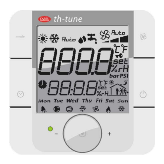
The room terminal (Option) The terminal supplied is equipped with a digital display, 4 buttons and a rotary encoder. Once installed in the premises, the device can measure the room temperature and enables remote control of the air handling unit. 1.3.1 Controls Button not used... -
Page 7: Displays
1.3.2 Displays Unit operating mode Main display area (Big area) Ventilation operating mode Ventilation operating speed Temperature unit Indicates whether the value displayed in the main area is a setpoint Indicates whether the value displayed in the main area is a humidity Indicates the active time slot zone Day of the week 10. -
Page 8: Room Terminal Information, Settings And Browsing
1.3.3 Room terminal information, settings and browsing The diagram below shows the various browsing, information and setting options on the room terminal: Terminal energising A few seconds (2-3s) u1.3 Terminal initialising A few seconds (2-3s) pressed Communication fault Unit on with the controller or Unit off (default... - Page 9 To find out the reference for the alarm, simply press the and "mode" buttons for 3s: To find out whether there is more than one active alarm, turn the encoder to access the full list. List of alarms: Messages Messages Room terminal HMI terminal AL01...
-
Page 10: Electrical Connections
Electrical connections 24VAC The room terminal and the controller are electrically connected using an AWG20/22 shielded cable (not supplied by CIAT) comprising two twisted pairs. The first and last controller must be no more than 500m apart. This network must never run parallel to power cables at a distance of less than 50 cm. -
Page 11: The Controller
The controller The descriptions of the terminals on the controller are provided below. Controller power supply (24Vac -25 RJ11 connector pGD1 VA maximum) configuration terminal (pLAN) 3-point connector to connect up other Passive sensors power supply units (pLAN) Configuration connector FIELDBUS port FIELDBUS port (configured in tLAN) -
Page 12: Functional Analysis Of The Control
Functional analysis of the control 1.6.1 Management of on and off modes Switching on OR critical fault Unit off On request AND on authorisation AND NO critical fault At least 1 override requested Unit powered up Off request Air flow rate OK Unit on Manual mode No override requested... -
Page 13: Fan Motors
1.6.5 Fan motors The motor or motors start when the unit is in "On" mode. The alarm feedback from the motor(s) is used to check their electronic switching protection. If one or other of these signals is not received, the unit is stopped and the faults are signalled. Their rotation speed is controlled using one of the 2 following modes: to maintain the fans at a constant flow ("Flow rate") in accordance with the setpoint(s) on page w0, based on the configuration on page p3 of the "Adjustment parameters"... -
Page 14: Temperature Control
1.6.7 Temperature control The regulated temperature may be: the return air temperature the room temperature the supply air temperature Two temperature control schemes are available: "Precision" mode, where a low deviation from the reference temperature is requested. "Energy optimisation" mode, where the key factor is the cost of energy. "Precision"... - Page 15 "Energy optimisation" mode: High Heating Cooling authorised threshold threshold authorised alarm alarm Deadband Return T° Ambient T° Heating Cooling Setpoint + 5°C Setpoint - 5°C setpoint setpoint Comfort: 23°C Comfort: 25°C Eco: 18°C Eco: 27°C Deadband: High threshold threshold Heating requirement (%) Cooling requirement (%) alarm alarm...
- Page 16 When the temperature drops, the controller will calculate the heat requirement needed to keep this temperature constant. This gradually adjusts the output of the 2 heating coils (via a 3-way valve for coil 1, via a triac or using 1 or 2 stages in the case of an electric heater) or a "Mixed"...
-
Page 17: Plate Recovery
If coil 2 is configured as Mixed, the action on its valve will be limited to prevent a drift in the temperature for the return network to the heat pump. If there is a fault with the heat pump (information received via a potential-free (dry) contact), an alarm will be displayed. Cooling mode Heating mode authorised... -
Page 18: Free Cooling
1.6.10 Free cooling The aim of this function is to make use of fresh outdoor air before starting to use the cooling coil to cool the building's supply air. This function is only available if there is a mixing box or a plate heat exchanger equipped with a bypass damper. Free Cooling management is based on actuating the mixing damper servomotor to alter the proportion of fresh air brought into the building and opening the plate heat exchanger bypass, if present. -
Page 19: Night Cooling
Maximum flow rate Rated flow Need for variation (%) 1.6.13 Night cooling The aim of this function is to use the coolness of fresh air from outdoors during the night within the building, with an option of over- ventilation, as far as the system will allow. This function is only available if there is a mixing box or a plate heat exchanger equipped with a bypass damper. -
Page 20: Controller Inputs And Outputs
Controller inputs and outputs 24Vac Shared 1.7.1 Analogue inputs Connector J3 Return air temperature sensor (Option) Supply air temperature sensor Fresh air temperature sensor (Option) Network water temperature sensor (Option) Supply air filter CF1 fouling level pressure sensor Supply air fan flow rate pressure sensor (Option) Return air fan flow rate pressure sensor (Option) Shared Connector J18... - Page 21 Connector J14 Maintenance alarms summary relay Shared Connector J15 Mixing damper opening control Mixing damper closing control NO10 Plate heat exchanger bypass damper control NO11 Insulation damper control NO12 Humidifier control Shared...
-
Page 22: Overview Of The Hmi Module Screens
Overview of the HMI module screens Esc button "Prg" button U :01 00:00 00.0°c U:01 Indicates the unit's address Indicates the request to switch the machine on or off 00.0°C Indicates the controlled temperature (ambient, exhaust or intake) 00:00 Indicates the time Indicates the state of the unit: on, off, on after a power failure, standby, switched off by a fault, switched off by CMS, post ventilation, manual mode Indicates "Heating"... -
Page 23: Access Level Selection Menu
2.1.1 Access level selection menu There are now three access levels: Level 1: User Level 2: Installer Level 3: Manufacturer Setpoint menu Comfort Indication of the operating mode. Level 2 access Fan flow rate Supply air 02000m3/h Supply air fan Comfort flow rate control setpoint Return air 02000m3/h Return air fan Comfort flow rate control setpoint... - Page 24 Comfort Indication of the operating mode for T° regulation in "Energy optimisation" mode Level 1 access Supply air Cooling 16.0°c Cooling Comfort Supply air temperature control setpoint (Regulated T° ≠ Supply air) (0 to 50.0°C) Eco 18.0°c Cooling Eco Supply air temperature control setpoint (Regulated T° ≠ Supply air) (0 to 50.0°C) Heating Comfort Supply air temperature control setpoint (Regulated T°...
-
Page 25: Machine Parameters Menu
Level 2 access Filter CF1 Filter dirty 0250Pa Dirty supply air filter 1 saturation level detection setpoint Filter clogged 0400Pa Blocked supply air filter 1 saturation level detection setpoint Level 3 access DX coil State 033.3% 066.6% DX coil on and off setpoint Level 3 access Changeover Heating... - Page 26 List of faults: Order Description Significance Danger Supply air motor Danger Return air motor Maintenance Supply air filter dirty Danger Supply air filter clogged Maintenance Return air filter CF1 dirty Danger Return air filter CF1 clogged Maintenance Filter CF2 dirty Maintenance Humidifier Danger...
- Page 27 Configuration Level 3 access Filter CF2 ---- Presence of a second filter at the inlet Return air unit ---- Filter CF2 : Without, With Return air unit: Without, With Configuration Level 3 access Heating coil ---- Cooling coil ---- Electric heater ---- Heating coil: Without: No coil...
-
Page 28: Adjustment Parameters Menu
Configuration Level 3 access Supply air fan K = ----- Return air fan K = ----- Supply air fan: K coefficient values for the Supply air fan Return air fan: K coefficient values for the Return air fan Adjustment parameters menu Level 1 access Language ------------... - Page 29 Level 2 access Regulated T° ---- Air quality ----- M factor 01.0 Proportionality factor value for Supply air duct flow rate and pressure control Quality band Air quality regulation proportional band Regulated T°: Supply, Return or Ambient air Air quality: Without, With (not available if the fans are monitored based on constant Supply air duct pressure) Supply air Level 2 access High T shift...
- Page 30 Level 3 access FC offset -3.0°c Outdoor T° offset from regulated T° for Free Cooling authorisation Prioritisation Level 3 access heating coils Start Coil 1 ---.- ---.- Coil 1 actuation start and end setpoint value Coil 2 ---.- ---.- Coil 2 actuation start and end setpoint value Level 3 access Coil distribution Electric with triac...
-
Page 31: Read-Only Parameters Menu
Input direction Level 3 access Supply air fan control Direction of the supply air fan sensor information during operation Antifreeze thermostat Direction of the antifreeze thermostat control information during operation CF2 pressure switch Direction of the filter CF2 pressure switch control information during operation Fire sensor Direction of the fire sensor control information during operation Elec heater safety... -
Page 32: Outputs
Level 1 access Supply air fan Supply air fan operation check state (C = on; O = off) Return air fan Return air fan operation check state (C = on; O = off) Fire Fire detection sensor check state (F = no fire; O = fire detected) Level 1 access Humidif. -
Page 33: Calculated Setpoints
Level 1 access Damper Damper control state (frost protection or insulation) Electric heater Stage 1 Electric heater stage 1 control state Stage 2 Electric heater stage 2 control state Level 1 access DX module DX module control state Humidifier Humidifier operation authorisation state Mixing ---% Mixing damper opening value... -
Page 34: Fault Memory Menu
Counters Electric heater Stage 1 -----h Reset - Electric heater stage 1 runtime counter reset and time Stage 2 -----h Reset - Electric heater stage 2 runtime counter reset and time Counters Humidifier -----h Reset- Humidifier runtime counter reset and time Counters DX module -----h... -
Page 35: Versions Menu
Versions menu U :01 PROGRAM AirCompact Control V 02.00 09/03/15 Bios: 06.08 Boot: 04.05 Indicates the reference of the program installed on the controller, the controller version and pLAN address. U :01 PROGRAM SO: -------- Order number for the unit... - Page 36 → → → Week1 Week2 Week3 Week4 Period 00:00 → 00:00 Period 00:00 → 00:00 Period 00:00 → 00:00 Period 00:00 → 00:00 State: State: State: State: --------------------- --------------------- --------------------- --------------------- □Sunday □Monday □Sunday □Monday □Sunday □Monday □Sunday □Monday □Tuesday □Wednesday □Tuesday □Wednesday...
-
Page 37: Communication Menu
Timer Daylight Saving Time and Standard Time switchover management activated Summer/Winter: ACTIVE Transit. time 060min Start:LAST SUNDAY in MARCH at 02.00 End:LAST SUNDAY in OCTOBER at 03.00 Communication menu SUPERVISION Level 3 access Protocol ----------- Choice of the communication protocol with the CMS (CAREL, LON, MODBUS RTU, KNX, WEB, MODBUS TCP) Speed ----- bauds Selection of the speed of communication with the CMS (4800 mandatory for LonWorks) - Page 38 If all the controller's outputs are overridden, the alarms will not be signalled on the door of the electrical box or on the display. Disconnecting the display will maintain the override and may result in damage to the hardware. This menu can only be accessed in level 3 and with the unit off. WARNING! ACTIVATION OF ALL OVERRIDES IS THE PROGRAMMER'S RESPONSIBILITY NONE OF THE SAFETY DEVICES IS OPERATIONAL...
-
Page 39: Access Level Menu
2.12 Access level menu Access levels Current level: 1 Displays the current level Access level 1 -> Visible only if the current level = 2 or 3, used to access or return to level 1 Level 2 access Visible only if the current level = 1 or 3, used to access or return to level 2 Level 3 access Visible only if the current level = 1 or 2, used to access or return to level 3 Access levels... -
Page 40: Master/Slave Menu
2.13 Master/Slave menu The Master/Slave function is used to manage several units (maximum of 8) supplying air to the same room and providing automatic weekly rotation (168 hours). This is done to ensure uniform wearing of the AHUs. A backup/additional function is also available. Additional ---- Unit within network... -
Page 41: Connecting A Remote Screen To The Plan
Connecting a remote screen to the pLAN A remote user terminal can be connected to each controller on the pLAN network (RS485) using two cards (CIAT code: 7122917) and one shielded cable consisting of three AWG24 twisted pairs and a shield. -
Page 42: Addressing The Plan
Addressing the pLAN Once the controllers are connected over the pLAN network, the controllers and the terminals must be addressed. There is a range of 32 possible addresses (binary logic). As a result, a total of 32 controllers and terminals can be connected over the pLAN network. -
Page 43: Assigning Private And Shared Terminals
• select the desired value using the buttons and confirm by pressing the button. If the value selected is different from that previously stored in memory, the mask of the screen below will appear and the new value will be stored in the display's permanent memory. -
Page 44: Checking The Plan Address
(Rs485, KNX, LON) or gateways (devices able to interpret various communication protocols) must be installed NOTE: If using a communication bus, the routing and processing of the available data are outside CIAT's scope of supply. They must be provided by the installer, and require the involvement of an integrator. ®... -
Page 45: The Datapoint Database
The components required for connection to the remote and/or local ModBus supervision system are as follows: An RS485 serial card (CIAT code: 7119749) connected to each controller. A standard RS485/USB converter for connection to a PC (not supplied by CIAT). The converter can be connected to any network RS485 card. -
Page 46: Modbus Tcp Connection
The codes for the Modbus functions used are: 1 or 2: Read n bits 3 or 4: Read multiple registers (16 bits) 5: Write one bit 6: Write one register 8: Read diagnostics counters 11: Read event counter 15: Write n bits 16: Write multiple registers (16 bits) NB: The JBus addresses are equal to the "Modbus address"... -
Page 47: Variables
5.3.4 Variables 5.3.4.1 Commands Register Register decimal Description Format Type Adjustable values hex. no. Registers accessible in read-only mode (function 1) and write mode (function 5) 0x118 Remote on/off command Boolean Read-only/Write 0: Off/1: On 0x119 Fault acknowledgement Boolean Read-only/Write 0: No/1: Acknowledgement 0x11A Electric heater load shedding... - Page 48 Return air fan flow rate control setpoint in "Night 0x1BC Integer Read-only/Write m3/h cooling" mode 0x1BD Stage 1 and off setpoint value for the electric heater Integer Read-only/Write 0x1BE Stage 1 on setpoint value for the electric heater Integer Read-only/Write 0x1BF Stage 2 off setpoint value for the electric heater Integer...
-
Page 49: Reading Parameters
5.3.4.3 Reading parameters Register Register decimal Description Format Type Values displayed hex. no. Dampers accessible in read-only mode (functions 3 or 4) 0x44C 1100 Supply air temperature Integer Read-only Value x10 0x44D 1101 Return air temperature Integer Read-only Value x10 0x44E 1102 Ambient temperature... - Page 50 0x49E 1182 Calculated supply air setpoint value Integer Read-only Value x10 0x4A5 1189 Supply air fan runtime counters Integer Read-only in hours 0x4A6 1190 Option to reset the counters Boolean Read/Write 1 = Reset 0x4AB 1195 Return air fan runtime counters Integer Read-only in hours...
-
Page 51: Alarms
5.3.4.4 Alarms Register Register decimal Description Format Type hex. no. Dampers accessible in read-only mode (functions 3 or 4) 0x514 1300 Level 0 fault (critical fault) Boolean 0 or 1 0x515 1301 Level 10 fault (Non-critical fault) Boolean 0 or 1 0x516 1302 Supply air motor alarm... -
Page 52: Lon
= board faulty Red fault LED: signals a board installation problem (connection, communication speed 4800bds) On request, the "Air_Technologies_110905.XIF" file is available. 5.4.1 LON scope of supply Recap of on-site LON tasks by CIAT/Installer/Integrator for commissioning: Task CIAT Integrator Installer Commissioning service Supply of .XIF integration file... - Page 53 bit 1 Return air motor alarm bit 2 Not used Supply air filter 1 dirty alarm bit 3 bit 4 Supply air filter 1 blocked alarm bit 5 Not used bit 6 Return air filter 2 dirty alarm bit 7 Return air filter 2 blocked alarm bit 8 Additional filter 3 dirty alarm...
-
Page 54: The Analogue Datapoints
5.4.3 The analogue datapoints Type Index NV name SNVT Direction Description nvo_custom_1 output Supply air filter CF1 fouling level nvo_custom_2 output Supply air duct pressure nvo_custom_3 output Return air filter CF1 fouling level nvo_custom_5 output Heat exchanger fouling nvo_custom_8 output Supply air fan flow rate nvo_custom_9 output... -
Page 55: Knx
The bus used is a TP1, with a transmission speed of 9600 Bds. This bus requires a special external power supply (supplied as an option; CIAT code: 7222279) 5.5.1 Description of KNX communication card Meaning Cause / solution Constantly lit... -
Page 56: Variables
5.5.2 Variables The KSet software for configuring the group addresses is provided alongside the Carel_plugin_21.PR4 file for the ETS3 software tool (not provided) (Carel_plugin_30.PR5 file for the ETS4 software (not provided)) and the CTA-V30.XML file for the database below: Datapoint Datapoint Datapoint Description... - Page 57 "Precision" mode 9.001 Control setpoint for WTempRegulEco DPT_Value_Temp the monitored Eco temperature in "Precision" mode 9.001 Control setpoint WTempRegulEco DPT_Value_Temp return for the monitored Eco temperature in "Precision" mode 9.001 Upper limit for the Limite MaxTSouffl DPT_Value_Temp calculated Supply air T°...
- Page 58 optimisation" mode 9.001 Control setpoint WTempRegulEcoChaud DPT_Value_Temp return for the monitored Eco Heating temperature in "Energy optimisation" mode 9.001 Control setpoint for WTempSoufflConfortFroid DPT_Value_Temp the Comfort Cooling supply air temperature in "Energy optimisation" mode 9.001 Control setpoint WTempSoufflConfortFroid DPT_Value_Temp return for the Comfort Cooling supply air temperature in "Energy optimisation"...
- Page 59 Bit 0 = Supply air motor alarm Bit 1 = Return air motor alarm Bit 2 = Not used Bit 3 = Supply air filter CF1 dirty alarm Bit 4 = Supply air filter CF1 blocked alarm Bit 5 = Not used Bit 6 = Return air filter CF1 dirty alarm Bit 7 = Return air filter...
- Page 60 machine actuation in Eco / Comfort mode COIL Flow rate-dependent ConfortEcoDebit DPT_Switch 1.001 machine actuation return in Eco / Comfort mode COIL Pressure-dependent ConfortEcoPression DPT_Switch 1.001 machine actuation in Eco / Comfort mode COIL Pressure-dependent ConfortEcoPression DPT_Switch 1.001 machine actuation return in Eco / Comfort mode COIL...
-
Page 62: Configuration Process
5.5.3 Configuration process The diagram below illustrates the phases of the "configuration process" required for configuring the card correctly: XML file kSET: XML file No group Enter the group complete addresses addresses ETS3 XML file ETS3 project ETS3 Assign the addresses Download XML file to Create the links to all the modules, and... - Page 63 . Select Import all . Using Files → "Open/Manage projects…", open the project named Carel_plugin_V2.1 (or above): . Open the project using Open, select the device "CAREL Plugin", right-click on the mouse and select Copy:...
-
Page 64: Assigning The Physical Address
. Open or create the final project for the system and right-click on the mouse to paste the CAREL plugin, once or more according to the number of CAREL devices to be integrated. The address of each device is automatically incremented. If necessary, you can manually change the address of a device in Properties. -
Page 65: Downloading The Xml File
5.5.7 Downloading the XML file You must be sure that: . the Bus wire network is drawn out and connected . the Bus is energised . the CAREL card is connected to the KNX network . the controller is powered on Use the mouse to select the controller to be configured, right-click to open the "Properties"... -
Page 66: Table Of Alarms
Table of alarms * All possible options are covered by this table Alarm Sources Causes Solutions Return air B1 or - Malfunction - Replace sensor Room or return air ambient air th-Tune - Sensor disconnected - Reconnect sensor temperature sensor - Room overheated - Revise room loads temperature too high... - Page 67 Appendix: Component table – Control code (Main flow) F2CV F2EV F2TV FCFV FCMV FCXV F2CFV F2CMV F2CXV FEFV FTFV Filter Without With Without With Without Without With With Without Without Without With With With Without With Coil 1 Without Without Heating Heating Elec Triac Elec Triac...
- Page 69 Fax: 04 79 42 42 10 info@ciat.fr - www.ciat.com This document is not legally binding. Compagnie Industrielle As part of our continuous drive to improve our products, CIAT reserves the right d’Applications Thermiques to make any technical modifications without prior notice.
Need help?
Do you have a question about the AirCompact Control and is the answer not in the manual?
Questions and answers