Table of Contents
Advertisement
Advertisement
Table of Contents

Related Manuals for CIAT COMFORT LINE


Summary of Contents for CIAT COMFORT LINE
- Page 1 EN7593856-01 06 - 2022 I n s t r u c t i o n m a n u a l...
-
Page 2: Table Of Contents
CONTENTS PAGE 1 UNPACKING, CHECKING and STORING THE UNIT 2 HANDLING 3 DESCRIPTION OF THE UNIT (Fig. 1) 3.1 Name plate (Fig.2) 3.2 Models 3.3 Dimensions and weight 4 INSTALLATION AND CONNECTIONS 4.1 Mechanical connections 4.2 Air connections 4.3 Hydraulic connections 4.4 Condensate pump draining connection 4.5 Connecting the condensate drain pump (option) 4.6 Electrical connections... - Page 3 COLIS PACKAGE +50°C COLIS / PACKAGE 35 kg COLIS PACKAGE -10°C...
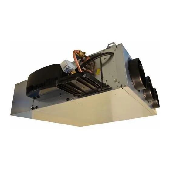
- Page 4 Fig. 1 COMFORT LINE™...
- Page 5 Masse/Weight en service kg Elec Diagram N° Declaration CE 7582176 7341384.00 700, av Jean Falconnier 01300 CULOZ (FRANCE) Tél.: 33 (0)4 79 42 42 42 www.ciat.com M a d e i n F r a n c e COMFORT LINE™...
- Page 6 Fig. 3 Fig. 4 COMFORT LINE™...
- Page 7 Fig. 5 Fig. 6 SIZES 83,5 55,5 111,6 83,5 55,5 111,6 COMFORT LINE™...
- Page 8 Fig. 7 Fig. 8 Fig. 9 COMFORT LINE™ VIII...
- Page 9 Fig. 10 Fig. 11 COMFORT LINE™...
- Page 10 Fig. 12 Fig. 13 COMFORT LINE™...
- Page 11 Fig. 14 Fig. 15 COMFORT LINE™...
- Page 12 Fig. 16 Fig. 17 COMFORT LINE™...
- Page 13 Fig. 18 Fig. 19 XIII COMFORT LINE™...
- Page 14 Fig. 20 Fig. 21 COMFORT LINE™...
- Page 15 Fig. 22 COMFORT LINE™...
- Page 16 Weight COMFORT LINE™ 19,3 23,8 27,4 29,5 LI Config 19,2 23,9 27,5 29,7 LY Config COMFORT LINE™...
- Page 17 XVII COMFORT LINE™...
- Page 18 Weight COMFORT LINE™ 20,5 25,5 26,1 35,1 U Standard 17,5 21,5 U Compact COMFORT LINE™ XVIII...
- Page 19 Weight COMFORT LINE™ 30,5 COMFORT LINE™...
-
Page 20: Unpacking, Checking And Storing The Unit
1 UNPACKING, CHECKING and STORING THE UNIT Thank you for purchasing a CIAT unit. We trust that this unit will give you complete satisfaction. To ensure correct operation, all connections (electrical, hydraulic, etc.) must be made in accordance with best industry practice and the regulations in force in the country of installation. -
Page 21: Description Of The Unit (Fig. 1)
Children must not play with the unit. User cleaning and maintenance must not be performed by children. The COMFORT LINE™ (CFL) range of fan coil units is used to heat or cool premises in the tertiary sector. COMFORT LINE™ can be ducted to the suction and on the supply air. -
Page 22: Models
Prior to installation, check that there will be sufficient space to allow maintenance and servicing work to be performed. COMFORT LINE™ must be secured to the ceiling or floor using 4 threaded rods either 6 mm or 8 mm in diameter (not supplied), which are fixed to the unit's 4 mounting systems using anti-vibration resilient mounts (optional, fig.3, a) or a nut/... -
Page 23: Air Connections
The coils are equipped (fig.7) with flat face swivel nuts with a female thread, diameter G ½˝ or G ¾˝ depending on the size of the unit, and an O-ring (supplied by CIAT). The manifold is equipped with an air bleed valve (fig.7, a), at the high point with partial draining at the low points (fig. - Page 24 - Installation CIAT does not guarantee the tightness of coil couplings equipped with O-rings for a tightening torque of over 18 N.m. During connection, always use a holding wrench on the component being connected to ensure the manifold is not twisted.
-
Page 25: Condensate Pump Draining Connection
CIAT shall not be liable for damage to valves caused by faulty design of the hydraulic supply network or incorrect commissioning. 4.4 Condensate pump draining connection Use a flexible and/or rigid drain pipe for a minimum slope of 1 cm/m, with a constant gradient along its whole length and no low points. -
Page 26: Electrical Connections
Before connecting the unit to the network, ensure that the voltage matches that indicated on the name plate. AC Asynchronous Motor Motor COMFORT LINE™ reference Max power input (W) 0,31 0,45 0,51... - Page 27 1,00 1,00 0,89 1,50 An earth connection is compulsory. CIAT shall not be liable for incidents resulting from faulty or non-existent earthing. Always follow the wiring diagram delivered with unit. To access the electrical terminal block: Disconnect the unit from the electrical power supply Use a Phillips screwdriver or a size 7 Allen key to undo the 2 screws securing the electrics box cover (Fig.9).
- Page 28 - With a controller or thermostat managing a 3-speed on/off control: Depending on the controller or thermostat, use the thermostat to select the ventilation speed to be modified, or use the "CIAT speed control unit" accessory supplied as an option. It is possible to change the speed (rpm), following the instructions supplied with the speed control unit.
- Page 29 Connecting COMFORT LINE™ to an air flow circuit alters its performance. The user must ensure that the minimum air flow rates indicated below are respected: AC Motor Brushless Motor Size 0 170 m /h (Speed 2*) 170 m /h (3,5 volts*)
-
Page 30: Servicing And Maintenance
COMFORT LINE™ is equipped with a G3 filter (optional). We recommend replacing it annually. The EPURE filter (optional) offers vastly superior filtration quality and a maintenance interval of up to two years under normal conditions of use. -
Page 31: Condensate Drain Pan
- Support the FMA platform as it is lowered, following the recesses (not present on T5 and T6) provided in the lateral panels (c). - Perform the steps in reverse to reassemble, taking care to ensure the insulation is not damaged. EN-31 COMFORT LINE™... - Page 32 - HEE Brushless motor with DFS: mark the wires which form the FMA wiring loom, then disconnect these from the terminal strip on the motor side - HEE Brushless motor without DFS - T6 only: disconnect the wiring loom from the motor using the connectors (supply and control) COMFORT LINE™ EN-32...
-
Page 33: Heat Exchange Coil
- Undo the 4 screws from the hydraulic coil (Fig.15) - Remove the removable upper panel (a) using the 4 screws. - Take the out coil from the top - Perform the steps in reverse to reassemble, taking care to ensure the insulation is not damaged EN-33 COMFORT LINE™... -
Page 34: Regulations
7 TESTING & WARRANTY All our units are tested and proven before leaving the factory. They are guaranteed against all manufacturing defects. CIAT shall not be held liable for any type of corrosion. CIAT's warranty does not cover damage resulting from incorrect electrical wiring, inadequate electrical or thermal protection or failure to use a filter. -
Page 35: Safety Considerations Relating To Final Shut-Down
The proportions of materials for each unit are listed in the Product Environmental Profile (PEP) available at the following website: http://www.pep-ecopassport.org/fr/ consulter-les-pep/ or on request from our departments. Any contaminated fluids must be disposed of by specialist professionals. EN-35 COMFORT LINE™... - Page 36 Manufacturer: Carrier S.C.S, Rte de Thil - 01120 Montluel, France. Printed in the European Union. Manufacturer reserves the right to change any product specifications without notice.
Need help?
Do you have a question about the COMFORT LINE and is the answer not in the manual?
Questions and answers