Table of Contents
Advertisement
Quick Links
Advertisement
Table of Contents

Summarization of Contents
Graphical Symbols and Safety Warnings
Electrical Hazard and Operational Warning Symbols
Explains hazard symbols and associated safety precautions in the manual.
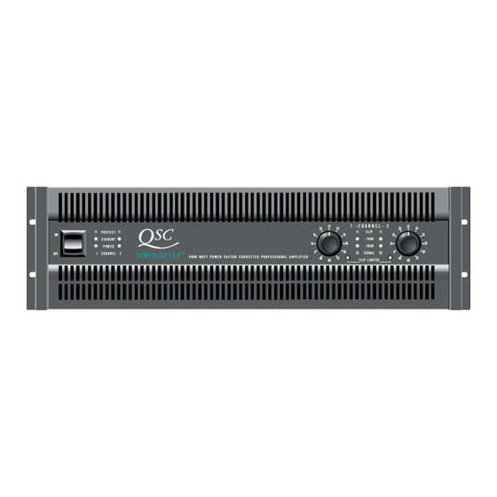
Front Panel Controls and Indicators
Power Switch, Status LEDs, and Mounting
Identifies power switch, status LEDs, and front panel mounting points.
Gain Controls and Clip Limiters
Describes gain controls and clip limiter switches per channel.
Channel Indicator LEDs
Details CLIP, -10dB, -20dB, and SIGNAL LEDs for channels.
Rear Panel Connections and Features
Input Terminals, Mode Switch, and Data Port
Describes input connectors, mode switch, and data port.
Output Terminals and Auxiliary Connections
Details output connectors, cooling fan, and power input.
Amplifier Mounting Procedures
Front and Rear Rack Mounting
Instructions for front rack mounting and optional rear rack ear installation.
Operating Voltage and Input Specifications
Correct Operating Voltage Requirements
Emphasizes selecting the correct AC mains voltage for safe operation.
Input Connector Types and Wiring
Explains "combo" connectors for balanced/unbalanced inputs and barrier strip wiring.
Data Port and Speaker Output Usage
Data Port Connectivity
Details the data port for connecting to external processors.
Speaker Output Wiring Guidelines
Provides guidelines and warnings for connecting speaker loads.
Amplifier Operation Features
Gain Controls and Remote Power
Explains gain adjustment and remote power supply control setup.
LED Indicator Guide
Status and Signal LED Meanings
Describes the meaning of PROTECT, STANDBY, POWER, CLIP, and SIGNAL LEDs.
Bridged Mono Mode Operation
Bridged Mono Safety and Setup
Covers safety precautions and gain control for bridged mono operation.
Bi-Amp Application with 1.5x and 1.6HVX Models
Input Connections for Bi-Amping
Details connecting an external crossover for bi-amp configurations.
PowerLight 2.4MB Input and Output
2.4MB Input Connectivity and Daisy-Chaining
Explains connecting the single input and daisy-chaining to other amplifiers.
2.4MB Output Configuration
Describes the parallel output terminals for speaker loads.
Amplifier Protection Features Part 1
Muting and Short Circuit Protection
Covers turn-on/off muting and Output Averaging™ short-circuit protection.
Clip Limiting Functionality
Explains how the clip limiter prevents continuous clipping.
Amplifier Protection Features Part 2
Thermal Shutdown and DC Fault Protection
Details thermal protection and amplifier shutdown on DC faults.
Input/Output Circuit Stability
Explains input isolation and ultrasonic network for load stability.


Need help?
Do you have a question about the PL-1.8 and is the answer not in the manual?
Questions and answers