
Related Manuals for Metallkraft PRM 60 FH


Summary of Contents for Metallkraft PRM 60 FH
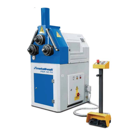
- Page 1 Operating Instructions Ring Bending Machine hydraulic PRM 50 FH PRM 60 FH PRM 50 FH...
- Page 2 Imprint Product identification Hydraulic Ring Bending Machine PRM 50 FH Item number: 3812036 PRM 60 FH Item number: 3812060 Manufacturer Stürmer Maschinen GmbH Dr.-Robert-Pfleger-Str. 26 D-96103 Hallstadt Fax: 0049 (0) 951 96555 - 55 E-Mail: info@metallkraft.de Internet: www.metallkraft.de Indications regarding the operating...
-
Page 3: Table Of Contents
11.3 Disposal of electrical equipment ............34 12 Spare parts...............34 12.1 Spare parts ordering ................. 34 12.2 Spare parts drawings PRM 50 FH ............ 35 12.3 Spare parts drawings PRM 60 FH ............ 37 13 Circuit diagrams ..............41 13.1 Hydraulic circuit diagram PRM 50 FH..........41 13.2 Hydraulic circuit diagram PRM 60 FH .......... -
Page 4: Introduction
Introduction Introduction You have made a good choice in purchasing a METALLKRAFT Ring Bending Machine. Thoroughly read the operating instructions before commissioning the machine. This informs about the proper commissioning, the intended use as well as the safe and efficient operation and maintenance of the machine. -
Page 5: Limitation Of Liability
Safety 1.3 Limitation of liability All Information and notes in these operating instructions were summarised ta- king the applicable standards and rules, the state-of-the-art and our long-term knowledge and experiences into consideration. In the following cases, the manufacturer assumes no liability for damages: - Failure to observe the operating instructions, - Improper use, - Use of untrained personnel,... -
Page 6: Responsibility Of The Operator
Safety ATTENTION! This combination of symbol and signal word indicates a potentially hazardous situation which, if not avoided, could result in property damage and environmental damage. NOTE! This combination of symbol and signal word indicates a po- tentially dangerous situation. It can lead to material and env- ironmental damage if it is not avoided. -
Page 7: Personnel Requirements
Safety 2.3 Personnel requirements Qualifications The various tasks described in this manual place different demands on the qualifications of the people entrusted with these tasks. WARNING! Danger due to insufficient qualification of per- sons! Insufficiently qualified persons can not assess the risks involved in handling the machine and expose themselves and others to the risk of serious or fatal injuries. -
Page 8: Personal Protective Equipment
Safety 2.4 Personal protective equipment Personal Protective Equipment is intended to protect people from compromi- sing safety and health at work. Personnel must wear personal protective equipment during the various operations on and with the machine, which are specifically indicated in the separate sections of this manual. The following section explains personal protective equipment:: Ear protection The goggles protect the eyes from flying parts and liquid... -
Page 9: Safety Equipment
Intended Use 2.6 Safety equipment WARNING! Danger to life due to non-functioning safety devices! Failure to operate or disable the safety equipment can result in serious injury or even death. - Before starting work, check that all safety equipment is in place and correctly installed. -
Page 10: Technical Data
The ring bending machine is equipped with a type plate with the following iden- tification data and CE marking (Fig. 3). Fig. 3: Type plate and CE marking of the ring bending machine PRM 50 FH PRM FH | Version 1.04 | EN... -
Page 11: Transport, Packaging, Storage
Transport, Packaging, Storage Transport, Packaging, Storage 5.1 Delivery and Transport Delivery Check the machine for visible transport damage after delivery. If the machine is damaged, it must be reported immediately to the transport company or the dealer. Improper transport is accident-prone and can cause damage or malfunctions Transport for which we do not grant any liability or guarantee. -
Page 12: Packaging
Transport, Packaging, Storage Danger points, unevenness and disturbance points must be inspected before transport. The removal of danger spots, disturbances and unevenness at the time of transport by other employees leads to considerable dangers. Careful planning of internal transport is therefore essential.. Transport with a forklift / pallet truck: For shipping, the machine is firmly mounted on a pallet so that it can be trans- ported by forklift or pallet truck. -
Page 13: Description Of Machine
7 Manometer 8 Lower roll, left 9 Upper roll 10 Guide roll left Fig. 5: Description of the ring bending machine PRM 50 FH 6.1 Scope of delivery Standard accessories - included The ring bending machine is delivered with - Standard bending rollers... -
Page 14: Assembly
- The site must have good lighting. Dimensions Fig. 6: Dimensions of the ring bending machines PRM 50 FH (left) and PRM 60 FH (right) The following size specifications should be taken into account at the place of installation or workplace (Fig. 7):... - Page 15 Assembly Fig. 7: Size specifications for sufficient space at the installation site of the ring bending machine. Left - vertical operation, right - horizontal operation - Space in front of and behind the machine: 1000 mm - Distance from the side of the machine to the wall: min. 1000 mm - de- pends on the size of the materials to be bent.
- Page 16 Assembly Setting up the ring bending machi- WARNING! Crushing! The machine may tilt during deployment and cause serious injury. - The machine must be set up by at least 2 people together. Use protective gloves! Wear safety boots! Wear protective clothes! The ring bending machine can be positioned horizontally or vertically for ma- chining workpieces (Fig.
-
Page 17: Commissioning
Step 1: Wrap a belt with a load capacity of approx. 1 ton around the shaft of the upper roller (PRM 50 FH - 1, Fig. 11) or hook it into the upper ring eye with a load hook for transport (PRM 60 FH, Fig. 11, right). -
Page 18: Connecting The Ring Bending Machine To The Mains Supply
Commissioning WARNING! Danger to life! There is a danger to life if these rules are not followed. - Never carry out work on the machine under the influence of alcohol, drugs or medication and/or in the event of fatigue or illnesses affecting concentration. - The machine may only be operated by qualified personnel. -
Page 19: Operation
Operation Connect the ring bending machine to the mains in the following steps: Step 1: The main switch must be switched off. Step 2: Connect the power cord to the mains. Step 3: Set the main switch from position "0" to "1". The power indicator (Pos.3, Fig. -
Page 20: Control Panel
Operation 9.1 Control panel 9.1.1Function assignment of the control elements Fig. 12: Control panel, right with digital display (optional) The control panel (Fig. 12) is provided with the following functions: 1 START button 2 EMERGENCY STOP button 3 Control button: Move upper roller upwards 4 Control button: Move upper roller down 5 Pedals: Right pedal: Rotation of the rollers, movement of the workpiece to the right. -
Page 21: Mounting The Standard Bending Rollers
Operation Step 1: Set the main switch on the electric box from "0" to "1". The display ( Pos. 3, Fig. 13) lights up. Step 2: Press the START button on the control panel to dtart the hydraulic pump. The machine is ready for operation. Step 3: Move the upper roller up and down with buttons 3 and 4 (Fig. -
Page 22: Adjusting The Lateral Guide Rolls
Operation 9.3 Adjusting the lateral guide rolls The bending of the workpiece can be corrected again with the aid of the lateral guide rollers. In addition, the lateral guide rollers are also used for special machining opera- tions, such as the manufacture of springs or spirals. Fig. - Page 23 Operation Functionality ATTENTION! The ring bending machine may only be operated from the front. The operator and other persons must not stand on the side of the ring bending machine during bending. The hands must be kept away from the rollers during operation. Step 1: Select suitable bending rollers for the material to be machined and mount correctly.
-
Page 24: Bending Rolls
Operation 9.4.1Bending of long profiles If long profiles have to be bent, please note the following. Fig. 18: Place long profiles on additional support surfaces Long profiles should be placed on additional support surfaces with rollers to re- lieve these as well as the ring bending machine (Fig. 18). Tips and recommendations At a vertically positioned ring bending machine to be bent profiles are easier to edit than a horizontally positioned ring... - Page 25 Operation Bending services maximum Size [mm] Mininmaler ben- Profile type ding diameter PRM 50FH [mm] 60FH PRM 50FH 60FH 50 x 6 80 x 9 1200 30 x 4 40 x 5 UPN 80 UPN 120 UPN 30 UPN 60 UPN 80 UPN 120 1200...
- Page 26 This results in a better sliding behaviour of the profile bar. Fig. 19: Cross section of standard rollers, PRM 50 FH (left) and PRM 60 FH (right). Top: upper roller, bottom: lower rollers PRM FH | Version 1.04 | EN...
- Page 27 Operation 9.5.3Possible applications for bending rollers Fig. 20: Application examples for bending rolls Fig. 21: Special rollers and special guide rollers for bending profiles PRM FH | Version 1.04 | EN...
-
Page 28: Bending Tolerances Of Different Profiles
Operation 9.6 Bending tolerances of different profiles Fig. 22: Bending tolerances of different profiles PRM FH | Version 1.04 | EN... -
Page 29: Maintenance, Servicing And Repair
Maintenance, servicing and repair Fig. 22: Bending tolerances of different profiles 10 Maintenance, servicing and repair Tips and recommendations To ensure, that the machine is always in good operating condition, regular care and maintenance work must be car- ried out. WARNING! Danger due to insufficient qualification of per- sons! -
Page 30: Hydraulic System
Maintenance, servicing and repair NOTE! After care, maintenance and repair work, check that all covers and protective devices have been properly fitted to the machine again and that no tools are left inside the machine or in its working area. Damaged protective devices and equipment parts must be repaired or replaced by customer service or a specialist workshop. -
Page 31: Gearbox
Maintenance, servicing and repair 10.2Gearbox Lubricate the gearbox, drive shafts and chains regularly on a monthly basis and check that they are running correctly. To do this, open the cover on the rear of the machine. Check all screws and rollers for tightness and tighten if necessary. -
Page 32: Change And Refill Oil
Maintenance, servicing and repair - Hydraulic unit: Hydraulic Oil ISO HV 46 (10 μ Filter) - For lubrication: Grease ISO XMO Equipment part Interval Lubricant Cleaning the rolllers daily Lubricate the roller bearings weekly Grease, oil Lubricating the guide roller bea- weekly Grease rings... -
Page 33: Malfunction, Possible Causes And Measures
Disposal, recycling of old equipment Type of oil Category C (ISO CC 150) Category H (ISO HV 46) Category X (ISO XM 0) SHELL OMALA OIL 150 TELLUS OEL T46 ALVANIA EP 0 HIFDROL HV46 SUPER GREASE EP 0 TEXACO MEROPA 150 RANDO OIL HD 46 MULTIFAK EP0... -
Page 34: Disposal Of Electrical Equipment
By ordering spare parts, send a copy of the spare parts drawing (2) with the marked part (engine) and marked positon number (3) to the dealer or spare parts department and provide the following information: - Type of machine:Ring Bending Machine PRM 50 FH - Item number:3812036 - Drawing number:2 - Position number:3 PRM FH | Version 1.04 | EN... -
Page 35: Spare Parts Drawings Prm 50 Fh
12.2Spare parts drawings PRM 50 FH The following spare parts drawings are intended to help identify the necessary spare parts. Spare parts drawing 1: Housing Fig. 25: Spare parts drawing 1 - Housing PRM 50 FH PRM FH | Version 1.04 | EN... - Page 36 Spare parts Spare parts drawing 2 Fig. 26: Spare parts drawing 2 - PRM 50 FH PRM FH | Version 1.04 | EN...
-
Page 37: Spare Parts Drawings Prm 60 Fh
Spare parts 12.3Spare parts drawings PRM 60 FH Spare parts drawing 1: Housing Fig. 27: Spare parts drawing 1 - Housing PRM 60 FH PRM FH | Version 1.04 | EN... - Page 38 Spare parts Spare pars drawing 2 Fig. 28: Spare parts drawing 2 - PRM 60 FH PRM FH | Version 1.04 | EN...
- Page 39 Spare parts Spare parts drawing 3 Fig. 29: Spare parts drawing 3 - PRM 60 FH PRM FH | Version 1.04 | EN...
- Page 40 Spare parts Spare parts drawing 4 Fig. 30: Spare parts drawing 4 - PRM 60 FH PRM FH | Version 1.04 | EN...
-
Page 41: Circuit Diagrams
Circuit diagrams 13 Circuit diagrams 13.1Hydraulic circuit diagram PRM 50 FH Fig. 31: Hydraulic circuit diagram PRM 50 FH 13.2 Hydraulic circuit diagram PRM 60 FH Fig. 32: Hydraulic circuit diagramr PRM 60 FH PRM FH | Version 1.04 | EN... -
Page 42: Electrical Circuit Diagrams Prm 50 Fh
Circuit diagrams 13.3Electrical circuit diagrams PRM 50 FH Electrical circuit diagram 1 Fig. 33: Electrical circuit diagram 1 - PRM 50 FH PRM FH | Version 1.04 | EN... - Page 43 Circuit diagrams Electrical circuit diagram 2 Fig. 34: Electrical circuit diagram 2 - PRM 50 FH PRM FH | Version 1.04 | EN...
- Page 44 Circuit diagrams Electrical circuit diagram 3 Grounding Grounding Grounding Grounding Fig. 35: Electrical circuit diagram 3 - PRM 50 FH PRM FH | Version 1.04 | EN...
-
Page 45: Electrical Circuit Diagrams Prm 60 Fh
Circuit diagrams 13.4Electrical circuit diagrams PRM 60 FH Electrical circuit diagram 1 Fig. 36: Electrical circuit diagram 1 - PRM 60 FH PRM FH | Version 1.04 | EN... - Page 46 Circuit diagrams Electrical circuit diagram 2 Fig. 37: Electrical circuit diagram 2 - PRM 100 FH PRM FH | Version 1.04 | EN...
- Page 47 Circuit diagrams Electrical circuit diagram 3 Grounding Grounding Grounding Grounding Fig. 38: Electrical circuit diagram 3 - PRM 60 FH PRM FH | Version 1.04 | EN...
-
Page 48: Ec Declaration Of Conformity
D-96103 Hallstadt hereby declares that the following product Product gruop: Metallkraft® Metalworking machines Type of machine: Ring Bending Machine Designation of machine*: Item number: PRM 50 FH 3812036 PRM 60 FH 3812060 Serial number*: ____________________ Year of manufacture*: 20____ *Fill in these fields according to the information on the type plate complies with all relevant provisions of the above-mentioned Directive as well as the other applicable Directives (hereaf- ter), including any changes in force at the time of declaration. -
Page 49: Notes
Notes 15 Notes PRM FH | Version 1.04 | EN... - Page 50 www.metallkraft.de...
Need help?
Do you have a question about the PRM 60 FH and is the answer not in the manual?
Questions and answers