Table of Contents
Advertisement
Quick Links
Advertisement
Table of Contents

Related Manuals for Metallkraft PRM 31F


Summary of Contents for Metallkraft PRM 31F
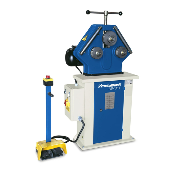
- Page 1 Operating Instructions Ring Bending Machine PRM 30 F PRM 31 F PRM 35 F PRM 30 F...
- Page 2 Imprint Product identification Ring Bending Machine PRM 30 F Item number: 381 2030 PRM 31 F Item number: 381 2031 PRM 35 F Item number: 381 2035 Manufacturer Stürmer Maschinen GmbH Dr.-Robert-Pfleger-Str. 26 D-96103 Hallstadt Fax: 0049 (0) 951 96555 - 55 Email: info@metallkraft.de...
-
Page 3: Table Of Contents
11.3 Disposal of lubricants................ 34 12 Spare parts...............34 12.1 Spare parts order ................35 12.2 Spare parts dawings PRM 30 F ............36 12.3 Spare parts drawing PRM 31 F ............38 12.4 Spare parts drawing PRM 35 F ............39 13 Electrical wiring diagrams ..........40... -
Page 4: Introduction
Introduction Introduction You have made a good choice in purchasing a METALLKRAFT Ring Bending Machine. Thoroughly read the operating instructions before commissioning the machine. This informs about the proper commissioning, the intended use as well as the safe and efficient operation and maintenance of the machine. -
Page 5: Limitation Of Liability
Safety 1.3 Limitation of liability All Information and notes in these operating instructions were summarised ta- king the applicable standards and rules, the state-of-the-art and our long-term knowledge and experiences into consideration. In the following cases, the manufacturer assumes no liability for damages: - Failure to observe the operating instructions, - Improper use, - Use of untrained personnel,... -
Page 6: Responsibility Of The Operator
Safety ATTENTION! This combination of symbol and signal word indicates a potentially hazardous situation which, if not avoided, could result in property damage and environmental damage. NOTE! This combination of symbol and signal word indicates a po- tentially dangerous situation. It can lead to material and env- ironmental damage if it is not avoided. -
Page 7: Personnel Requirements
Safety 2.3 Personnel requirements 2.3.1 Qualifications The various tasks described in this manual place different demands on the qualifications of the people entrusted with these tasks. WARNING! Danger due to insufficient qualification of per- sons! Insufficiently qualified persons can not assess the risks involved in handling the machine and expose themselves and others to the risk of serious or fatal injuries. -
Page 8: Personal Protective Equipment
Safety 2.4 Personal protective equipment Personal Protective Equipment is intended to protect people from compromi- sing safety and health at work. Personnel must wear personal protective equipment during the various operations on and with the machine, which are specifically indicated in the separate sections of this manual. The following section explains personal protective equipment:: Ear protection The goggles protect the eyes from flying parts and liquid... -
Page 9: Safety Equipment
Safety 2.6 Safety equipment WARNING! Danger to life due to non-functioning safety devices! Failure to operate or disable the safety equipment can result in serious injury or even death. - Before starting work, check that all safety equipment is in place and correctly installed. -
Page 10: Intended Use
Technical Data General data PRM 30 F PRM 31 F PRM 35 F Shaft Diameter 30 mm... -
Page 11: Type Plate
The nameplate with the following data for identification as well as the CE mar- king are attached to the ring bending machine (Fig. 3). Fig. 3: Type plate and CE marking of the ring bending machine PRM 30 F Transport, Packaging, Storage 5.1 Delivery and Transport... - Page 12 Transport, Packaging, Storage General risks during internal transport WARNING: DANGER OF TIPPING The device may be lifted unsecured by a maximum of 2cm. Employees must be outside the danger zone, the reach of loads. Warn employees and, if necessary, advise employees of the hazard. Devices may only be transported by authorized and qualified persons.
-
Page 13: Packaging
Transport, Packaging, Storage 5.2 Packaging All packaging materials and packaging aids used in the machine are recycla- ble and must always be recycled. Cardboard packaging components must be shredded for collection of waste paper. The foils are made of polyethylene (PE) and the upholstery parts made of poly- styrene (PS). -
Page 14: Description Of Device
Description of device Description of device Illustrations in this operating manual serve the general understanding and may deviate from the actual design. 1 spindle for height adjustment of upper roll 2 adjusting screw of the lateral guide roller 3 Side guide roller on the right 4 Upper role 5 Lower roll right 6 main switches... -
Page 15: Assembly
- The site must have good lighting. PRM 30 F The PRM 30 F has a swiveling machine head and can thus be used horizon- tally and vertically. The following dimensions should be taken into account at the place of installation or at the workplace (Fig. 6 and 7) Fig. - Page 16 Assembly To tilt the machine head for horizontal operation, proceed as follows: Step 1: Loosen the screw 1 (Fig. 6, right side). Step 2: Tilt the machine head 90 °. Step 3: Screw the screw 1 into the thread 2 (Fig. 6, right side). PRM 31 F The PRM 31 F can be used horizontally and vertically.
- Page 17 Assembly PRM 35 F The following dimensions should be taken into account at the place of installa- tion or at the workplace (Fig. 9) Fig. 9: Space requirement of the ring bending machine PRM 35 F-left vertical operation, right horizontal operations - Space in front of and behind the machine: 1000 mm - Distance from the side of the machine to the wall: at least 1000 mm - depends on the sizes of the materials to be bent...
- Page 18 Assembly Setting up the ring bending machine WARNING! Crushing! The machine may tilt during deployment and cause serious injury. - The machine must be set up by at least 2 people together. Wear safety gloves! Wear safety shoes! Wear protective clothing! Step 1: Check the ground with a spirit level for horizontal alignment, if neces- sary, compensate for slight unevenness.
-
Page 19: Commissioning
Commissioning The ring bending machine PRM 35 F can be set up horizontally or vertically for the machining of workpieces (Fig. 12). Fig. 12: Ring bending machine PRM 35 F - horizontal and vertical use To change the machine to the horizontal working position, proceed as follows: Step 1: Loop a belt or a steel cable with a load capacity of approx. - Page 20 Commissioning WARNING! Danger to life! There is danger to life if these rules are not followed. - Never carry out any work on the machine under the influ- ence of alcohol, drugs or medication and / or in case of fati- gue or concentration-impairing illnesses.
-
Page 21: Connect The Ring Bending Machine To The Mains
Operation 8.1 Connect the ring bending machine to the mains DANGER! Danger to life due to electric current! There is an immediate danger of electrocution on contact with live components. - The machine may only be connected by qualified electricians. - Work on the electrical system should only be carried out by qualified electricians. -
Page 22: Controls
Operation NOTE! Please observe the following before operating the machine. - The mains voltage must correspond to the voltage specifi- cations on the rating plate. - The main switch must be set to "0". - The safety devices as well as the protective covers must be functional. -
Page 23: Mount Standard Bending Rollers
Operation ATTENTION! Please make sure that the emergency switch is reset to its original position after use. If the emergency switch remains activated, the machine will not start. Step 4: Insert material, move the rollers with the pedals and carry out the ben- ding work. -
Page 24: Adjust Side Guide Rollers
Operation NOTE! All spacers must always be applied to the shaft to ensure correct seating of the rollers. Finally, push the unneeded spacers onto the shaft and make sure that the rollers are tight after tightening the nuts. 9.3 Adjust side guide rollers With the aid of the lateral guide rollers, the bending of the workpiece can be corrected again. - Page 25 Operation NOTE! The first and last 200 mm - 300 mm of the profile to be bent do not reach the desired rounding value. For this reason, the blank blank must be made longer and the profile cut again after bending. Functionality Step 1: Select suitable bending rollers for the material to be machined and mount correctly.
- Page 26 Operation Check the radius. If the desired radius has not yet been reached, adjust it by turning the upper roller up and down. Often several operations are necessary. It must be done carefully so as not to exceed the desired level. Once the desi- red radius has been reached, the entire profile can be bent.
-
Page 27: Bending Rolls
9.5 Bending rolls Bending options with bending rol- Bending services maximum Size [mm] Mininmaler bending lers Profile type PRM 30 F diameter [mm] PRM 31 F PRM 30/31 F 35 F 35 F Bending possibilities with standard bending rolls: 30 x 30... - Page 28 Operation Standard roles The ring bending machines are supplied with a set of standard rollers which, when arranged, are capable of bending most of the hot rolled profiles com- monly found on the market. It is important that the rollers are well aligned on the machine and arranged in the most favorable position for the particular profile type.
-
Page 29: Application Examples For Bending Rolls
Operation 9.6 Application examples for bending rolls Fig. 22: Application examples for bending rolls Fig. 23: Special rollers and special guide rollers for bending profiles PRM F | Version 1.07 | EN... -
Page 30: Bending Tolerances Of Different Profiles
Operation 9.7 Bending tolerances of different profiles PRM F | Version 1.07 | EN... -
Page 31: Cleaning And Maintenance
Cleaning and maintenance Fig. 24: Bending tolerances of different profiles 10 Cleaning and maintenance Tips and recommendations To ensure that the machine is always in good operating con- dition, regular care and maintenance work must be carried out. WARNING! Danger due to insufficient qualification of per- sons! Insufficiently and / or fatally injured. -
Page 32: Cleaning
Cleaning and maintenance Wear safety gloves! Wear safety shoes! Wear protective clothing! 10.1 Cleaning Clean the rollers of the ring bending machine daily. Attention: do not use oil or grease! The rollers and material must be clean and grippy to allow the material to bend without slipping. -
Page 33: Lubrication
Cleaning and maintenance 10.2 Lubrication Fig. 25: Lubrication points on the ring bending machine Equipment part Interval Lubricant Thread of the spindle Every day Grease Bearings of rollers, waves weekly Grease, Oil Bearings of guide rollers weekly Grease Drive chain half-yearly Grease 10.3 Cleaning the electrical box... -
Page 34: Disposal, Recycling Of Old Equipment
Disposal, Recycling of old equipment 11 Disposal, Recycling of old equipment In the interests of the environment, care must be taken to ensure that all compo- nents of the machine are disposed of in the proper and approved way. 11.1 Decommission Disused machinery and machine components must be taken out of service im- mediately in order to avoid later misuse and endangering the environment or people. -
Page 35: Spare Parts Order
Example: The upper shaft for the ring bending machine PRM 30 F has to be ordered. This is indicated in the spare part drawing 2 with the item number 18. -
Page 36: Spare Parts Dawings Prm 30 F
The following spare parts drawings is intended to help identify the necessary spare parts. To order, send a copy of the parts drawing with the parts marked to the authorized dealer. Fig. 26: Spare parts drawing 1 - Housing and frame PRM 30 F PRM F | Version 1.07 | EN... - Page 37 Spare parts Fig. 27: Spare parts drawing 2 - PRM 30 F PRM F | Version 1.07 | EN...
-
Page 38: Spare Parts Drawing Prm 31 F
Spare parts 12.3 Spare parts drawing PRM 31 F Fig. 28: Spare parts drawing 1 - PRM 31 F PRM F | Version 1.07 | EN... -
Page 39: Spare Parts Drawing Prm 35 F
Spare parts 12.4 Spare parts drawing PRM 35 F Fig. 29: Spare parts drawing 1 - PRM 35 F PRM F | Version 1.07 | EN... -
Page 40: Electrical Wiring Diagrams
Electrical wiring diagrams 13 Electrical wiring diagrams 13.1 Electrical wiring diagram PRM 30 F Fig. 30: Electrical circuit diagram 1 for PRM 30 F PRM F | Version 1.07 | EN... - Page 41 Electrical wiring diagrams Fig. 31: Electrical circuit diagram 2 for PRM 30 F PRM F | Version 1.07 | EN...
-
Page 42: Electrical Wiring Diagrams Prm 31 F
Electrical wiring diagrams 13.2 Electrical wiring diagrams PRM 31 F Electronic wiring diagram 1: Motor und Control Group Abb. 32: Electrical circuit diagram 2 for PRM 31 F: PRM F | Version 1.07 | EN... - Page 43 Electrical wiring diagrams Electronic wiring diagram 2: Control Group Fig. 33: Electrical circuit diagram 2 for PRM 31 F PRM F | Version 1.07 | EN...
- Page 44 Electrical wiring diagrams Electronic wiring diagram 3: Electrical Cabinet Scheme Fig. 34: Electrical circuit diagram 3 for PRM 31 F PRM F | Version 1.07 | EN...
-
Page 45: Electrical Wiring Diagrams Prm 35 F
Electrical wiring diagrams 13.3 Electrical wiring diagrams PRM 35 F Fig. 35: Electrical wiring diagram 1 for PRM 35 F PRM F | Version 1.07 | EN... - Page 46 Electrical wiring diagrams Fig. 36: Electrical wiring diagram 2 for PRM 35 F PRM F | Version 1.07 | EN...
-
Page 47: Ec Declaration Of Conformity
D-96103 Hallstadt hereby declares that the following product Product gruop: Metallkraft® Metalworking machines Type of machine: Ring Bending Machine Designation of the machine *: PRM 30 F Item number *: 3812030 PRM 31 F 3812031 PRM 35 F 3812035 ____________________... - Page 48 www.metallkraft.de...
Need help?
Do you have a question about the PRM 31F and is the answer not in the manual?
Questions and answers