Sign In
Upload
Download
Table of Contents
Contents
Add to my manuals
Delete from my manuals
Share
URL of this page:
HTML Link:
Bookmark this page
Add
Manual will be automatically added to "My Manuals"
Print this page
×
Bookmark added
×
Added to my manuals
Manuals
Brands
CESAB Manuals
Forklifts
C4E200
Service manual
CESAB C4E200 Service Manual
Hide thumbs
1
2
3
4
5
6
7
8
9
10
11
12
13
14
15
16
17
18
19
20
21
22
23
24
25
26
27
28
29
30
31
32
33
34
35
36
37
38
39
40
41
42
43
44
45
46
47
48
49
50
51
52
53
54
55
56
57
58
59
60
61
62
63
64
65
66
67
68
69
70
71
72
73
74
75
76
77
78
79
80
81
82
83
84
85
86
87
88
89
90
91
92
93
94
95
96
97
98
99
100
101
102
103
104
105
106
107
108
109
110
111
112
113
114
115
116
117
118
119
120
121
122
123
124
125
126
127
128
129
130
131
132
133
134
135
136
137
138
139
140
141
142
143
144
145
146
147
148
149
150
151
152
153
154
155
156
157
158
159
160
161
162
163
164
165
166
167
168
169
170
171
172
173
174
175
176
177
178
179
180
181
182
183
184
185
186
187
188
189
190
191
192
193
194
195
196
197
198
199
200
201
202
203
204
205
206
207
208
209
210
211
212
213
214
215
216
217
218
219
220
221
222
223
224
225
226
227
228
229
230
231
232
233
234
Table Of Contents
235
page
of
235
Go
/
235
Contents
Table of Contents
Bookmarks
Table of Contents
Index
General Information
General Information Index
Technical Data
Chassis Index
Truck’s Lay out
Description of Main Parts
Operator's Seat
Foot Pedals Version
Foot Drive Direction
Direction Selector Lever
Steering Column Push Buttons
Selected Setting Push Button
Speed Reduction Push Putton
Load Handling Commands
Levers Unit
Battery Cover
Battery Plug Fixing Position
Dashboard
Dashboard Controls
Battery Charge Status Indicator
Diagnostic Code Alphanumeric Display
Selected Setting Display
Plates
Identification Plate
Capacity Plate
Load Plate
Lifting of the Truck
Hook Attachment Points for Lifting the Truck
Lifting of the Forklift Truck with Cabin
Motors/ Engines
Motors / Engines Index
Electrical Motors Characteristics
Traction Motors
Lifting Motor
Electrical Motors Arrangement
Transmission / Drive Gear
Transmission / Drive Gear Index
Reduction Gear View
Reduction Gear Maintenance
Drive Unit
Changing the Oil in the Reduction Gears
Every 1000 Hours
Replacement of the Reduction Gear
Brakes / Wheels Index
Brake System
Service Brake
Service Brake Control
Brake Oil Tank
Parking Brake Control and Adjustment
Brake Operating System Description
Brake Disks
Replacement of the Wheel Brake Cylinder
Standard Tyres
Safety of Rims and Wheels for Forklift Trucks
Tightening Torques
Steering System
Steering System Index
Steering Control
Power Steering Hydraulic Diagram
Steering Cylinder
3 And 4 Wheels Version
Power Steering Setting
Pressure Setting
3 Wheels Version
4 Wheels Version
3-Wheel Steering Axle
Control of Steering Unit
Steering Potentiometer Fixing
4-Wheel Steering Axle
Steering Axle Check
Max Steering Angle
Bearing Adjustment
Steering Wheels
Electric & Electronic System
Electric & Electronic System Index
Table of Contents
Battery and Battery Charger
Battery Charging Warnings
Approximate Density Data
General Indications for Battery Maintenance
Electrical Motor Characteristic
Encoder
Motor Signals Connector
Main Electrical Components Description
Accelerator Pedal
Set the Potentiometer
Fuse Box
Fuse Description
24 Volt Fuses
DC/DC Converter
Electronic Panels (Technical Specifications)
Operational Features
Diagnosis
General Precautions
Protections
Thermal Protection
External Agents
Connection of the Auxiliary Circuit - Dual Ac2 Unit Traction
Cables Assembly Instructions
Connectors
Enabling of C10 Speed Reduction
Traction Electric Block Diagram
Transducer Steering-Wheel with Potentiometer
Steering System
Steering Potentiometer (3 Wheels)
Steering Potentiometer (4 Wheels)
Connection of the Electric Circuit - Ac2 Unit Lifting
Lifting Electric Block Diagram
Electrical Circuit Connection
Dual Ac2 Traction Unit and Ac2 Lifting Unit
Necessary Setting after Replacing the Traction Logic Unit
Necessary Setting after Replacing the Lifting Logic Unit
Can-Bus and Onboard Commands Diagram
Arm Commands
Can - Bus Description
Controller Area Network
Arm Card
Settings
Joysticks
Fingertip
Light Card
Connector Description
I/O Card
Input / Output Card
Horn Electric Connection
Mhyrio Card
Potentiometer Configuration
Arm Command (Joysticks / Fingertips Version)
Accelerator Potentiometer Configuration
Values Optained by the Console
Values Optained by the Multimeter
Lifting Potentiometer Configuration
Console Function
General Description
Console Function General Description
Hour Meter
Parameter Change
Tester
Keyboard
Console Connection
Lifting Unit
Traction Unit
Dual Ac2 Master Traction Unit
Parameter Change
Alarms Functions
Dual Ac2 Traction Master Unit
Code Alarm
Ac2 Lifting Unit
Parameter Setting Table
Dual Ac2 Traction Unit
Description of the Console Standard Menu
Dual Ac2 Traction Unit Master Menu
Dual Ac2 Traction Unit Slave Menu
Lifting
Mhirio
Alarm
Hydraulic / Pneumatic System Index
Hydraulic Diagram
Control Valve Version
Lifting Performance
Tilting and Sideshift Performance
Tilting and Sideshift
Joysticks / Fingertips Version
Lifting Equipment Oil and Oil Filter
To Change Oil and Filter
Pump Replacement
Mast Group
Triple Mast Section
Lifting Cylinders on the Mast
Telescopic Cylinder Without Braking Effect
Description of the Cylinder Components
Cylinder Checking Methods
Lubrication of Lifting Equipment
Masts
Fork Carriage and Sideshift Unit
Security Installations Control
Safety Fork Carriage End Stop
Guide Rollers and Guide Shoes Replacing
Fork Carriage Guide Shoes Replacing
Mast Chains Inspection
Positioning the Fork Mounting Carriage
Checking the Chains
Fork Inspections
General Criteria
Legibility of Marking
Mast Group Tilting Setting
Attachement
Maintenance Tables
Maintenance Tables Index
Oil and Grease Specifications
Running-In Maintenance Times Table
Safety Information Index
Safety Information
Work Clothes
Work Place
Electric Part
Charging of the Battery
Welding
Truck Washing
Advertisement
Quick Links
1
Diagnostic Code Alphanumeric Display
Download this manual
SERVICE MANUAL
036-0410-07
C3E120
C4E120
C3E150
C4E150
C3E160
C4E160
C3E160L C4E160L
C3E180
C4E180
C3E180L C4E180L
C3E200
C4E200
04/2005
Table of
Contents
Previous
Page
Next
Page
1
2
3
4
5
Advertisement
Table of Contents
Need help?
Do you have a question about the C4E200 and is the answer not in the manual?
Ask a question
Questions and answers
Related Manuals for CESAB C4E200
Forklifts CESAB BT BLITZ 312 Service Manual
(235 pages)
Forklifts CESAB C3E150 Service Manual
(235 pages)
Forklifts CESAB C3E160 Service Manual
(235 pages)
Forklifts CESAB C3E180 Service Manual
(235 pages)
Forklifts CESAB R200 Series Product Manual
Reach trucks 1.2 - 1.6 tonne. (40 pages)
Forklifts CESAB S210 Repair Manual
(324 pages)
Forklifts CESAB B 200 Repair Manual
(460 pages)
Forklifts CESAB R214 Product Manual
Reach trucks 1.2 - 1.6 tonne. (40 pages)
Forklifts CESAB R216 Product Manual
Reach trucks 1.2 - 1.6 tonne. (40 pages)
Forklifts CESAB S212L Repair Manual
(324 pages)
Forklifts CESAB S214L Repair Manual
(324 pages)
Forklifts CESAB B 215 Repair Manual
(460 pages)
Summarization of Contents
General Information
Technical Data
Technical specifications and data for the truck models.
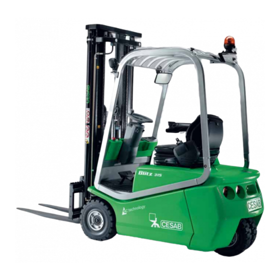
Chassis
Truck's Lay Out
Diagram and identification of main truck components.
Operator Controls and Interface
Details of foot pedals, drive levers, and buttons for operator control.
Steering Column Control Buttons
Explanation of setting and speed reduction push buttons.
Load Handling Control Options
Description of joystick, control valve, and fingertip commands.
Dashboard Instruments and Indicators
Identification and purpose of dashboard instruments and warning lights.
Truck Identification and Capacity Plates
Details on identification and capacity plates for truck data.
Safe Truck Lifting Procedures
Procedures and equipment for safely lifting the truck.
Motors / Engines
Traction Motor Specifications
Technical specifications for traction electric motors.
Lifting Motor Specifications
Technical specifications for the lifting electric motor.
Transmission / Drive Gear
Reduction Gear View
Diagram illustrating the internal components of the reduction gear.
Drive Unit Oil Maintenance
Procedures for checking and changing oil in the reduction gears.
Drive Unit Replacement Procedure
Steps for replacing the reduction gear assembly.
Brakes / Wheels
Service Brake System Operation
Description of the service brake system and control intervals.
Parking Brake Control and Adjustment
Details on parking brake operation, control, and adjustment.
Brake Disks
Exploded view and explanation of brake disk assembly.
Wheel Brake Cylinder Replacement
Procedures for replacing the wheel brake cylinder.
Tyre Specifications and Safety
Information on tyre types, safety, and tightening torques.
Steering System
Steering System Operation
Description of steering operation and pressure setting.
Power Steering Hydraulic Diagram
Schematic illustrating the power steering hydraulic circuit.
3-Wheel Steering Axle Maintenance
Maintenance and checks for the 3-wheel steering axle.
Steering Wheel Bearing Adjustment
Procedure for adjusting steering wheel bearings.
Electric & Electronic System
Battery Maintenance and Charging Safety
General indications for battery maintenance and charging warnings.
Electric Motor Technical Data
Technical specifications for traction and lifting motors.
Encoder Function and Wiring
Function and wiring of the motor encoder.
Key Electrical Component Identification
Identification of key electrical components like modules and contactors.
Fuse Box and Fuse Details
Location and description of fuses and fuse box.
DC/DC Converter Specifications
Information on the DC/DC converter and equipment consumption.
Electronic Panel Technical Specs
Technical specifications for traction and lifting electronic panels.
Truck Operational Characteristics
Description of the truck's operational characteristics and functions.
System Diagnosis and Alarm Codes
How the system diagnoses faults and lists alarms.
General Electrical Safety Precautions
Important safety precautions related to electrical components.
Traction Unit Electrical Connections
Wiring diagram for the traction unit connections.
Electrical Connector Pinouts
Detailed description of various connectors used in the system.
Speed Reduction Feature Enablement
How to enable/disable speed reduction feature.
Electronic Steering System Overview
Description of electronic steering system for 3 and 4 wheel versions.
Steering Potentiometer Calibration
Voltage values and configuration for steering potentiometers.
Lifting Unit Electrical Connections
Wiring diagram for the lifting unit connections.
Console Operation and Functions
Overview of console functions like hour meter, parameter change, tester.
Traction Unit Parameter Configuration
Explanation of parameters for the DUAL AC2 Master Traction Unit.
Using the Tester for Diagnostics
How to use the tester function for diagnostics.
Traction Unit Alarm Codes
List and description of alarm codes for the traction unit.
Battery Indicator Operation
How the battery indicator works and how to adjust it.
Battery Adjustment Parameter Maps
Console values for battery adjustment and indicator reset.
Hydraulic / Pneumatic System
Hydraulic Diagram (Control Valve)
Hydraulic diagram for the control valve system.
Hydraulic Diagram (Joysticks/Fingertips)
Hydraulic diagram for joystick/fingertip control valve systems.
Electric Control Valve Components
Description and numbering of hydraulic electric control valves.
Lifting Performance Data
Performance data for lifting operations of standard machines.
Tilting & Sideshift Performance Data
Performance data for tilting and sideshift operations.
Hydraulic Oil and Filter Maintenance
Procedures for checking and changing hydraulic oil and filter.
Hydraulic Pump Replacement
Steps for replacing the hydraulic pump.
Mast Group
Mast Group Construction Details
Description of mast profiles, cylinders, and features.
Triple Mast Section Diagram
Diagram of a triple mast section with its components.
Mast Lifting Cylinder Configurations
Illustrations of lifting cylinders for different mast types.
Central Cylinder Braking Effect
Description of the central cylinder's braking effect mechanism.
Side Displacement Cylinder Braking
Description of the side displacement cylinder's braking effect.
Telescopic Cylinder Description
Description of the telescopic cylinder's braking effect.
Hydraulic Cylinder Performance Checks
Procedures for checking cylinder seals and performance.
Lifting Equipment Lubrication Schedule
Lubrication schedule and points for masts and fork carriage.
Fork Carriage Guide Shoe Replacement
Steps for replacing fork carriage guide shoes and shims.
Mast Chain Inspection and Replacement
Inspection and replacement of mast chains and tie rods.
Fork Arm Inspection Criteria
Visual inspection criteria for fork arms and their wear.
Attachement
Options
Maintenance Tables
Lubricants and Grease Specifications
Specifications for hydraulic oils and greases used in the truck.
Tyre and Fastener Tightening Torques
Torque values for wheel and drive unit fasteners.
Initial Running-in Maintenance Schedule
Initial maintenance schedule for new trucks.
Periodic Maintenance Schedule
Periodic maintenance intervals for various truck components.
Safety Information
Workplace Safety and Attire
Recommended attire and safe working environment requirements.
Truck Lifting Safety Precautions
Procedures and tools for safely lifting the truck.
Electrical System Safety Precautions
Safety precautions related to the truck's electrical system.
Welding and Grinding Safety
Safety measures to be taken during welding operations.
Safe Truck Washing Practices
Precautions when washing the truck, especially around electrical parts.
Table of Contents
Save PDF
Print
Rename the bookmark
Delete bookmark?
Delete from my manuals?
Login
Sign In
OR
Sign in with Facebook
Sign in with Google
Upload manual
Upload from disk
Upload from URL
Need help?
Do you have a question about the C4E200 and is the answer not in the manual?
Questions and answers