Table of Contents
Advertisement
Quick Links
KEEP FOR FUTURE REFERENCE
INSTRUCTIONS
International Version
MODEL NUMBERS: P11004DC,
P.O. Box 368 – 908 West Main
Laurel, MT USA 59044
P1HV1104DC, P11104DC
phone 800-548-7341
SERIAL NUMBER: ___________
phone 406-628-8231
fax 406-628-8354
(please see serial label and record number here)
SINGLE-CHANNEL LIFTER
DC-VOLTAGE
READ ALL INSTRUCTIONS AND WARNINGS
BEFORE OPERATING THIS LIFTER
DESIGNED FOR THE MATERIALS HANDLING PROFESSIONAL
Advertisement
Table of Contents

Related Manuals for WOOD'S POWR-GRIP P11104DC


Summary of Contents for WOOD'S POWR-GRIP P11104DC
- Page 1 KEEP FOR FUTURE REFERENCE INSTRUCTIONS International Version MODEL NUMBERS: P11004DC, P.O. Box 368 – 908 West Main Laurel, MT USA 59044 P1HV1104DC, P11104DC phone 800-548-7341 SERIAL NUMBER: ___________ phone 406-628-8231 fax 406-628-8354 (please see serial label and record number here)
-
Page 3: Table Of Contents
TABLE OF CONTENTS SPECIFICATIONS ......................3 WARNINGS ........................4 OPERATING FEATURES ....................5 ASSEMBLY ........................6 INTENDED USE ....................... 7 ......................7 HARACTERISTICS ......................8 PERATING NVIRONMENT ......................8 ISPOSAL OF THE IFTER OPERATION ........................9 ......................9 EFORE SING THE IFTER Taking Safety Precautions .......................... - Page 4 MAINTENANCE ......................17 ......................17 NSPECTION CHEDULE Every-Lift Inspection ..........................17 Frequent Inspection ...........................17 Periodic Inspection .............................17 Infrequent Use............................18 ........................18 ESTING CHEDULE Operational Tests ............................18 Load Test ..............................18 ......................19 AINTENANCE CHEDULE ......................... 19 ATTERY ......................... 19 ATTERY ECHARGE ......................20 ATTERY HARGER ......................
-
Page 5: Specifications
Designed for use with a crane or other hoisting equipment, P1-04DC lifters employ vacuum to hold a load for lifting, and they provide manual 180° rotation and manual 90° tilt movements for load manipulation. Model Number: P11004DC P1HV1104DC P11104DC Vacuum Pads: (Four, standard rubber, with #60 filter screen) 10"... -
Page 6: Warnings
Wood’s Powr-Grip cannot be responsible for the safety of a lifter that has been modified by the customer. For consultation, contact Wood's Powr-Grip (see LIMITED WARRANTY). Never disengage both the rotation latch and the tilt latch at the same time. -
Page 7: Operating Features
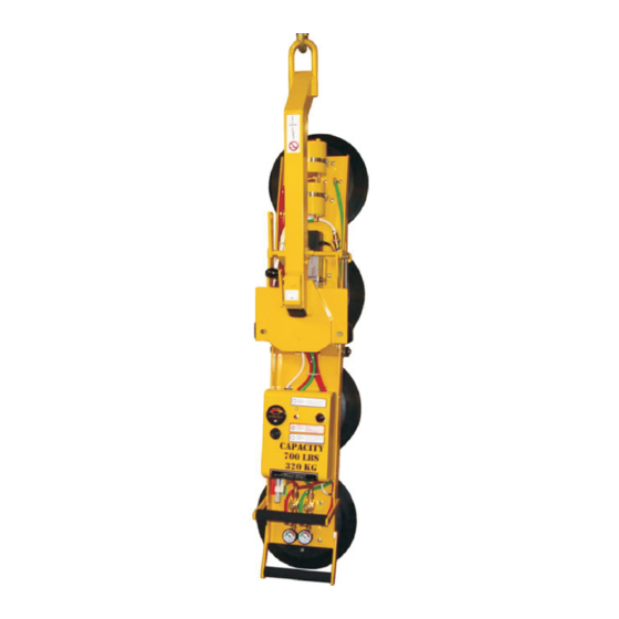
OPERATING FEATURES Note: Components featured in the following instructions for assembling, operating or maintaining the vacuum lifter are underlined on their first appearance in each section. Standard P11104DC shown. 7 Enclosure with VACUUM PUMP, 1 LIFT BAIL VACUUM SWITCH, and LOW VACUUM 13 VALVE HANDLE 2 LIFT BAR WARNING BUZZER (if applicable) -
Page 8: Assembly
ASSEMBLY 1) Open the shipping container and remove all materials for restraining or protecting the vacuum lifter. Save the container for use whenever the lifter is transported. 2) Suspend the lifter from a crane as follows: Select hoisting equipment (crane and hoist, when applicable) rated to carry the maximum load weight plus the lifter weight (see SPECIFICATIONS: Maximum Load Capacity and Lifter Weight). -
Page 9: Intended Use
: Friction Coefficient), as ACUUM AINTENANCE verified by a friction test. If necessary, contact Wood's Powr-Grip for help in conducting a friction test. • In order to avoid damaging the vacuum pads, the load's surface temperature must not exceed the allowable Operating Temperatures (see SPECIFICATIONS). However, if such an... -
Page 10: Operating Environment
PERATING NVIRONMENT The operator must determine whether the lifter is intended to be used in each work environment, in accordance with the following restrictions: WARNING: Never use lifter in dangerous environments. • This lifter is not intended for use in any environment that is inherently dangerous to the operator or likely to compromise the lifter's ability to function. -
Page 11: Operation
OPERATION EFORE SING THE IFTER The operator must determine whether the lifter is capable of performing each intended task, in INSTRUCTIONS accordance with the SPECIFICATIONS and INTENDED USE sections of this manual. In addition, all of the following preparations must be completed prior to lifting any load. Taking Safety Precautions The operator must be trained in all relevant industry and regulatory standards for the operation of the vacuum lifter in its geographical location (eg, ASME B30.20 in the USA). -
Page 12: T O Apply The Pads To A Load
the alarm volume must exceed ambient noise by In order to be considered clearly audible, at least 15 dBA at the operator position. Since the Maximum Alarm Volume is 103 dBA, ambient noise must not exceed 88 dBA under any circumstances. Furthermore, if ambient noise measures 88 dBA, the alarm volume must be set to maximum and the operator must remain within 2 ft [60 cm] of the warning buzzer, in order for it to be effective. -
Page 13: Reading The Vacuum Gauge
Reading the Vacuum Gauge green The vacuum gauge indicates the current vacuum level in the lifter’s vacuum system. The range indicates vacuum levels sufficient for lifting the maximum load weight, whereas the range indicates vacuum levels that are sufficient for lifting the maximum load weight. The gauge needle should show a sudden surge in vacuum as the vacuum pads seal against the load. -
Page 14: T O Lift And Move The Load
IFT AND OVE THE Positioning the Lift Bar WARNING: Lift bar must be oriented vertically to lift load. Never lift the load from a flat position with the lift bar latched parallel to the load. Always disengage the tilt latch (see T ILT THE follow) and raise the lift bar to a vertical orientation before attempting to lift. -
Page 15: Monitoring The Low Vacuum Warning Buzzer (If Applicable)
Monitoring the Low Vacuum Warning Buzzer (if applicable) If the lifter is equipped with a low vacuum warning buzzer, an alarm sounds until the lifter attains sufficient vacuum to lift the maximum load weight (see SPECIFICATIONS: Load Capacity). After the lifter has attained this vacuum level, the alarm stops sounding, to indicate that the lifter is ready to lift the load. -
Page 16: T O Rotate The Load Edgewise
OTATE THE DGEWISE WARNING: Never disengage both the rotation latch and the tilt latch at the same time. This lifter is not designed for rotation and tilt functions to be used at the same time. Disengaging the rotation and tilt latches simultaneously could cause uncontrolled and unpredictable load movement, potentially resulting in load damage or injury to the operator. -
Page 17: T O Release The Pads From The Load
ILT THE WARNING: Never disengage both the rotation latch and the tilt latch at the same time This lifter is not designed for rotation and tilt functions to be used at the same time. Disengaging the rotation and tilt latches simultaneously could cause uncontrolled and unpredictable load movement, potentially resulting in load damage or injury to the operator. -
Page 18: After Using The Lifter
FTER SING THE IFTER Leave the valve handle in the “RELEASE” position (power off). CAUTION: Do not set the lifter against any surfaces which could soil or damage the vacuum pads. The control handle at the end of the pad channel can be used to support an unloaded lifter when not suspended from a crane: Make sure the pad channel is oriented vertically with the control handle at the bottom. -
Page 19: Maintenance
MAINTENANCE WARNING: Always make sure battery is disconnected before servicing lifter. INSTRUCTIONS Note: One or more wiring diagrams are provided in the final section of this manual for reference when servicing the lifter or trouble-shooting a deficiency. NSPECTION CHEDULE Perform inspections routinely, according to the following frequency schedule: Every-Lift Inspection •... -
Page 20: Infrequent Use
• Keep a written record of all Periodic Inspections. If any deficiency is detected during the inspection, correct it before using the lifter. If necessary, return the lifter to Powr-Grip or an authorized dealer for repair (see LIMITED WARRANTY). Infrequent Use each time If a lifter is used less than 1 day in a 2-week period, perform the Periodic Inspection before using the lifter... -
Page 21: Maintenance Schedule
ATTERY ECHARGE Only use a battery charger supplied by or approved by Wood's Powr-Grip; other chargers may reduce battery life. Charge the battery as soon as possible after any extended use of the lifter, or whenever the battery gauge indicates diminished energy (see B preceding). -
Page 22: Attery Harger Est
In addition, all pads should be replaced on a regular basis, preferably after no more than 2 years, to ensure that the friction coefficient is not compromised. If necessary, contact your dealer or Wood's Powr-Grip for more information. Inspection Inspect each vacuum pad for the following deficiencies routinely, as directed in the preceding and T . -
Page 23: Cleaning
• Filter screen missing from pad face: This screen helps prevent debris from plugging the vacuum hose and the air filter. Replace any missing screen immediately (see REPLACEMENT PARTS LIST). • Nicks, cuts or abrasions in sealing edges: Pad damage can reduce the lifting capacity of the lifter. -
Page 24: Vacuum Test
ACUUM Test the vacuum system for leakage routinely, as directed in the preceding I NSPECTION ESTING CHEDULES 1) Clean the face of each vacuum pad as previously directed (see V ACUUM AINTENANCE Cleaning). 2) Apply the lifter to a clean, smooth, nonporous surface. The surface should be flat or possess no more curvature than the lifter is designed for (if any). -
Page 25: Air Filter Maintenance − Small
− S ILTER AINTENANCE MALL (for 1 oz [30 ml] bowl size filters) Filter Function and Conditions Requiring Service An air filter prevents solid particles and liquid from contaminating components in the vacuum system. CAUTION: Examine air filter regularly and empty when necessary. Liquid must not contact any portion of the filter element;... -
Page 26: Vacuum Pump Maintenance − Dynaflo Dv1032102
− D DV1032102 ACUUM AINTENANCE YNAFLO WARNING: Before proceeding with any maintenance, disconnect power source. If the vacuum pump takes too long to attain full vacuum, it may require maintenance. Replace the diaphragm, gasket/flap valves or (when preferable) the entire head assembly (see REPLACEMENT PARTS LIST), as necessary to obtain acceptable pump performance. -
Page 27: Vacuum Pump Maintenance − Thomas 107Cdc20
− T 107CDC20 ACUUM AINTENANCE HOMAS WARNING: Before proceeding with any maintenance, disconnect power source. If the vacuum pump (14) takes too long to attain full vacuum, it may require maintenance. Replace the diaphragm, valve flappers or head gasket as necessary to obtain acceptable pump performance (see REPLACEMENT PARTS LIST). -
Page 28: Vacuum Switch Adjustment
ACUUM WITCH DJUSTMENT Vacuum Switch Function A vacuum switch controls the low vacuum warning light and the vacuum pump (see OPERATING FEATURES for location of vacuum switch): The valve handle activates the warning light and the pump, which evacuates the vacuum pads. After the lifter attains a vacuum level sufficient for lifting the maximum load weight (hereafter, “minimum lifting level”), the vacuum switch automatically turns off the pump and the warning light. -
Page 29: Adjustment Procedure
Adjustment Procedure WARNING: Lifting capacity decreases whenever vacuum switch is adjusted to maintain lower vacuum level. 1) Using a 1/4" open-end wrench (as provided), turn the adjustment screw about 1/6th turn at a time (approximately one flat of the screw head). lower clockwise To maintain a... -
Page 30: Replacement Parts List
Rotation Release Lever Knob 15632 Pad Filter Screen - Small (for G0750 pad) 15630 Pad Filter Screen - Large (for G3370 & HV11 pads) SERVICE ONLY WITH IDENTICAL REPLACEMENT PARTS SUPPLIED BY OR APPROVED BY WOOD'S POWR-GRIP CO., INC. Rev 26.0/6-13 P1-DC: #35111... -
Page 31: Limited Warranty
For purchases in Contact your dealer or the Technical Service Department at Wood’s Powr-Grip Co. for assistance. Wood's Powr-Grip Co., Inc. 908 West Main St. / P.O. Box 368 Laurel, MT USA 59044 phone 800-548-7341 phone 406-628-8231 fax 406-628-8354 Rev 26.0/6-13... - Page 32 Rev 26.0/6-13 P1-DC: #35111...
- Page 33 Rev 26.0/6-13 P1-DC: #35111...
- Page 34 Rev 26.0/6-13 P1-DC: #35111...
Need help?
Do you have a question about the P11104DC and is the answer not in the manual?
Questions and answers