Table of Contents
Advertisement
Quick Links
KEEP FOR FUTURE REFERENCE
INSTRUCTIONS
International Version
MODEL NUMBERS: MRTA611LDC,
P.O. Box 368 – 908 West Main
Laurel, MT USA 59044
MRTA6HV11FDC, MRTA610DCO
phone 800-548-7341
SERIAL NUMBER: ___________
phone 406-628-8231
fax 406-628-8354
(please see serial label and record number here)
QUADRA-TILT ROTATOR
DC-VOLTAGE
WITH DUAL VACUUM SYSTEM
READ ALL INSTRUCTIONS AND WARNINGS
BEFORE OPERATING THIS LIFTER
DESIGNED FOR THE MATERIALS HANDLING PROFESSIONAL
Advertisement
Table of Contents

Related Manuals for WOOD'S POWR-GRIP MRTA611LDC


Summary of Contents for WOOD'S POWR-GRIP MRTA611LDC
- Page 1 KEEP FOR FUTURE REFERENCE INSTRUCTIONS International Version MODEL NUMBERS: MRTA611LDC, P.O. Box 368 – 908 West Main Laurel, MT USA 59044 MRTA6HV11FDC, MRTA610DCO phone 800-548-7341 SERIAL NUMBER: ___________ phone 406-628-8231 fax 406-628-8354 (please see serial label and record number here)
-
Page 3: Table Of Contents
TABLE OF CONTENTS SPECIFICATIONS ......................3 WARNINGS ........................4 OPERATING FEATURES ....................5 ASSEMBLY ........................6 ........................ 6 ET UP THE IFTER ................7 HANGE THE RAME ONFIGURATION To Connect/Disconnect Vacuum Hoses ......................8 To Reposition (or Remove) Movable Pad Mounts ................... 9 To Install/Remove Extension Arms ........................ - Page 4 MAINTENANCE ......................20 ......................20 NSPECTION CHEDULE Every-Lift Inspection ..........................20 Frequent Inspection ...........................20 Periodic Inspection .............................20 Infrequent Use............................21 ........................21 ESTING CHEDULE Operational Tests ............................21 Load Test ..............................21 ......................22 AINTENANCE CHEDULE ......................... 22 ATTERY ......................... 22 ATTERY ECHARGE ......................23 ATTERY HARGER ......................
-
Page 5: Specifications
Pad Spread and Maximum Load Capacity HANGE THE RAME ONFIGURATION for many of the possible MRTA611LDC pad frame configurations. Load Capacity is based on a friction coefficient of 1; see MAINTENANCE: V : Friction Coefficient for ACUUM AINTENANCE additional information. -
Page 6: Warnings
Wood’s Powr-Grip cannot be responsible for the safety of a lifter that has been modified by the customer. For consultation, contact Wood's Powr-Grip (see LIMITED WARRANTY). Rev 14.0/5-13 MRTA6-DC: #35072... -
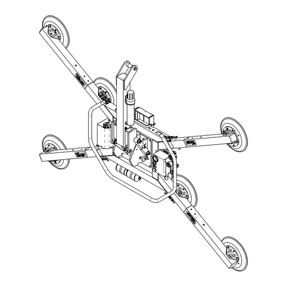
Page 7: Operating Features
OPERATING FEATURES Note: Components featured in the following instructions for assembling, operating or maintaining the vacuum lifter are underlined on their first appearance in each section. Standard MRTA611LDC shown. 1 LIFT SPOOL 8 BATTERY TEST BUTTON 16 Cover for VACUUM PUMP... -
Page 8: Assembly
ASSEMBLY ET UP THE IFTER 1) Open the shipping container and remove all materials for restraining or protecting the vacuum lifter. Save the container for use whenever the lifter is transported. 2) Suspend the lifter from a crane as follows: Select hoisting equipment (crane and hoist, when applicable) rated to carry the maximum load weight plus the lifter weight (see SPECIFICATIONS: Maximum Load Capacity and Lifter Weight). -
Page 9: T O Change The Pad Frame Configuration
(see SPECIFICATIONS: Pad Spread and Load Capacity). The following illustration shows several possible configurations. Select a configuration to provide optimal support across the load surface and to minimize load overhang (see OPERATION: B EFORE SING THE IFTER Standard MRTA611LDC pad frame shown. Rev 14.0/5-13 MRTA6-DC: #35072... -
Page 10: To Connect/Disconnect Vacuum Hoses
Configurations are created by installing or removing the pad frame’s extension arms, by repositioning or removing the movable pad mounts, and by connecting or disconnecting the vacuum hoses to certain vacuum pads. Always assemble the pad frame in a symmetrical arrangement, to keep the lifter balanced (see illustration). -
Page 11: To Reposition (Or Remove) Movable Pad Mounts
To Reposition (or Remove) Movable Pad Mounts 1) Remove the cotterless hitch pin from one movable pad mount by pulling on the pull ring. 2) Move the pad mount to the desired position on the pad frame and align the holes for the cotterless hitch pin in the pad mount COTTERLESS HITCH PIN with the corresponding holes in the pad frame. -
Page 12: Intended Use
: Friction Coefficient), as ACUUM AINTENANCE verified by a friction test. If necessary, contact Wood's Powr-Grip for help in conducting a friction test. • In order to avoid damaging the vacuum pads, the load's surface temperature must not exceed the allowable Operating Temperatures (see SPECIFICATIONS). However, if such an... -
Page 13: Operating Environment
Conversely, allowable thickness increases as load weight decreases. In addition, an operator may be able to manually counteract the tendency of unstable loads to tilt out of the upright position, provided that the operator maintains control of the load at all times (see OPERATION: T : About the Tilt Linkage and T ). -
Page 14: Operation
OPERATION EFORE SING THE IFTER The operator must determine whether the lifter is capable of performing each intended task, in INSTRUCTIONS accordance with the SPECIFICATIONS and INTENDED USE sections of this manual. In addition, all of the following preparations must be completed prior to lifting any load. Taking Safety Precautions The operator must be trained in all relevant industry and regulatory standards for the operation of the vacuum lifter in its geographical location (eg, ASME B30.20 in the USA). -
Page 15: Confirming The Pad Frame Configuration
CAUTION: Examine each air filter regularly, and empty when necessary. Two air filters help protect the vacuum generating system from contaminants. However, the lifter is not intended for use on wet load surfaces because the filters would not prevent liquid from entering the vacuum system. -
Page 16: Reading The Vacuum Gauges
Note: If a vacuum pad has been lying against a hard object (as during shipping), it may be slightly distorted. Although initially it may be difficult to apply the pad to a load, this condition should correct itself with continued use. Reading the Vacuum Gauges The lifter is equipped with 2 vacuum gauges, which indicate the current vacuum level in each green... -
Page 17: About The Tilt Linkage
IFT AND OVE THE About the Tilt Linkage WARNING: Make sure load is positioned correctly on lifter; unbalanced loads may tilt unexpectedly. The lifter’s tilt linkage is designed to automatically hold a balanced load in either the upright or the flat position. However, an unbalanced load may tilt unexpectedly from the flat position to the upright position, or vice versa, when lifted. -
Page 18: Monitoring Vacuum Indicators
Monitoring Vacuum Indicators The low vacuum warning light and both vacuum gauges must remain completely visible to the operator, so that they can be monitored throughout the entire lift. WARNING: Vacuum indicators must be visible to operator throughout entire lift. If the vacuum system experiences leakage while the lifter is attached to the load, the vacuum pump turns on automatically, as required to maintain sufficient vacuum for lifting the maximum load weight. -
Page 19: Controlling The Lifter And Load
Controlling the Lifter and Load When the vacuum indicators show that the lifter is ready, use the hoisting equipment to raise the lifter and load as needed to clear any obstacles in their path. Use the control handle to keep the lifter and load in the desired orientation while they are suspended from the crane. -
Page 20: T O Tilt The Load
ILT THE WARNING: Always keep hands and fingers away from bars of tilt linkage. Remember that the load requires more vertical space when tilted to the upright position, as well as more horizontal space when tilted to the flat position. Make sure there is sufficient clearance for the load to tilt without contacting the operator or any nearby objects. -
Page 21: After Using The Lifter
FTER SING THE IFTER Leave the valve handle in the “RELEASE” position (power off). CAUTION: Do not set the lifter against any surfaces which could soil or damage the vacuum pads. Use the hoisting equipment to gently lower the lifter onto a stable support; then detach the hoisting equipment hook from the lift spool. -
Page 22: Maintenance
MAINTENANCE WARNING: Always make sure battery is disconnected before servicing lifter. INSTRUCTIONS Note: One or more wiring diagrams are provided in the final section of this manual for reference when servicing the lifter or trouble-shooting a deficiency. NSPECTION CHEDULE Perform inspections routinely, according to the following frequency schedule: Every-Lift Inspection •... -
Page 23: Infrequent Use
• Keep a written record of all Periodic Inspections. If any deficiency is detected during the inspection, correct it before using the lifter. If necessary, return the lifter to Powr-Grip or an authorized dealer for repair (see LIMITED WARRANTY). Infrequent Use each time If a lifter is used less than 1 day in a 2-week period, perform the Periodic Inspection before using the lifter... -
Page 24: Maintenance Schedule
ATTERY ECHARGE Only use a battery charger supplied by or approved by Wood's Powr-Grip; other chargers may reduce battery life. Charge the battery as soon as possible after any extended use of the lifter, or whenever the battery gauge indicates diminished energy (see B preceding). -
Page 25: Attery Harger Est
In addition, all pads should be replaced on a regular basis, preferably after no more than 2 years, to ensure that the friction coefficient is not compromised. If necessary, contact your dealer or Wood's Powr-Grip for more information. Inspection Inspect each vacuum pad for the following deficiencies routinely, as directed in the preceding and T . -
Page 26: Cleaning
• Filter screen missing from pad face: This screen helps prevent debris from plugging the vacuum hose and the air filter. Replace any missing screen immediately (see REPLACEMENT PARTS LIST). • Nicks, cuts or abrasions in sealing edges: Pad damage can reduce the lifting capacity of the lifter. -
Page 27: Vacuum Test
ACUUM Test the vacuum system for leakage routinely, as directed in the preceding I NSPECTION ESTING CHEDULES 1) Clean the face of each vacuum pad as previously directed (see V ACUUM AINTENANCE Cleaning). 2) Apply the lifter to a clean, smooth, nonporous surface. The surface should be flat or possess no more curvature than the lifter is designed for (if any). -
Page 28: Air Filter Maintenance
ILTER AINTENANCE (for brass bowl type filters) Filter Function and Conditions Requiring Service An air filter prevents solid particles from contaminating components in the vacuum system. CAUTION: Examine air filter regularly and empty when necessary. Open each filter regularly to determine whether liquid or other contaminants are trapped inside. Remove any liquid or contaminants found in the filter bowl. -
Page 29: Vacuum Pump Maintenance − Dynaflo Dv1032102
− D DV1032102 ACUUM AINTENANCE YNAFLO WARNING: Before proceeding with any maintenance, disconnect power source. If the vacuum pump takes too long to attain full vacuum, it may require maintenance. Replace the diaphragm, gasket/flap valves or (when preferable) the entire head assembly (see REPLACEMENT PARTS LIST), as necessary to obtain acceptable pump performance. -
Page 30: Vacuum Pump Maintenance − Thomas 107Cdc20
− T 107CDC20 ACUUM AINTENANCE HOMAS WARNING: Before proceeding with any maintenance, disconnect power source. If the vacuum pump (14) takes too long to attain full vacuum, it may require maintenance. Replace the diaphragm, valve flappers or head gasket as necessary to obtain acceptable pump performance (see REPLACEMENT PARTS LIST). -
Page 31: Vacuum Switch Adjustment
ACUUM WITCH DJUSTMENT Vacuum Switch Function A vacuum switch controls the low vacuum warning light and the vacuum pump (see OPERATING FEATURES for location of vacuum switch): The valve handle activates the warning light and the pump, which evacuates the vacuum pads. After the lifter attains a vacuum level sufficient for lifting the maximum load weight (hereafter, “minimum lifting level”), the vacuum switch automatically turns off the pump and the warning light. -
Page 32: Adjustment Procedure
Adjustment Procedure WARNING: Lifting capacity decreases whenever vacuum switch is adjusted to maintain lower vacuum level. 1) Using a 1/4" open-end wrench (as provided), turn the adjustment screw about 1/6th turn at a time (approximately one flat of the screw head). lower clockwise To maintain a... -
Page 33: Replacement Parts List
Clamp Collar - 2.157-18 Thread - 1-Piece 10900 Shoulder Bolt - Socket Head - 5/16" x 1/2" x 1/4-20 Thread (for mounting pads) SERVICE ONLY WITH IDENTICAL REPLACEMENT PARTS SUPPLIED BY OR APPROVED BY WOOD'S POWR-GRIP CO., INC. Rev 14.0/5-13 MRTA6-DC: #35072... -
Page 34: Limited Warranty
For purchases in Contact your dealer or the Technical Service Department at Wood’s Powr-Grip Co. for assistance. Wood's Powr-Grip Co., Inc. 908 West Main St. / P.O. Box 368 Laurel, MT USA 59044 phone 800-548-7341 phone 406-628-8231 fax 406-628-8354 Rev 14.0/5-13... - Page 35 Rev 14.0/5-13 MRTA6-DC: #35072...
Need help?
Do you have a question about the MRTA611LDC and is the answer not in the manual?
Questions and answers