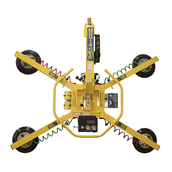
Summary of Contents for WOOD'S POWR-GRIP MRT4-DC
- Page 1 LEAK TEST PROCEDURE MRT4-DC LIFTERS ― SINGLE VACUUM SYSTEMS TESTING AND MAINTENANCE MUST BE DONE BY A QUALIFIED PERSON KEEP FOR FUTURE REFERENCE TST-011 – Rev. 2013-049 Page 1 of 12...
- Page 2 THIS PAGE INTENTIONALLY LEFT BLANK TST-011 – Rev. 2013-049 Page 2 of 12...
- Page 3 SYMPTOMS OF VACUUM LEAK Severe leakage is evidenced by a lifter’s inability to draw full vacuum while attached to a clean, smooth, nonporous surface. In such cases, the vacuum pump will run continuously and the vacuum level shown on the vacuum gauge will be less than 16" Hg [-54 kPa], the red zone of the vacuum gauge.
-
Page 4: Preliminary Test
PRELIMINARY TEST This test determines whether leakage is located in the vacuum generating system or the pad system. CAUTION: Disconnect the battery before removing the vacuum generating system cover. 1) Carefully remove the valve enclosure cover ( ) and lay it to one side, so that exposed wire terminals do not touch any conductive material, as... - Page 5 VACUUM GENERATING SYSTEM TEST Note: The following assumes that you have access to suitable plugs, a ball valve with vacuum gauge, and a short additional piece of hose for connecting the ball valve to the lifter’s vacuum lines and fittings. The most likely leak points in the vacuum generating system are the check valve, the filter assembly, or the control valve.
- Page 6 Test the hose assembly from the pump and vacuum tank to the valve assembly for leakage: 1) Remove the ball valve from the vacuum pump and reattach the original hose to the pump. 2) Remove the hose ( connecting the pump and tank to the valve, from the 90°...
- Page 7 Test the control valve / filter assembly for leakage: 1) Remove the ball valve from the valve assembly and reattach the original hose to the valve’s 90° hose nipple. 2) Remove the hose from the filter that connects it to the vacuum gauge assembly ( 3) Attach a short piece of hose to the end of the ball valve...
- Page 8 Note, the MRT4-DC vacuum hoses are routed through the pad frame itself. The only fittings that can be accessed externally are the pad fittings and (on lifters with coiled red poly hose to vacuum pads) couplings that connect the coiled hoses to the (internal) straight hoses and fittings.
- Page 9 [for lifters with coiled red poly hose to vacuum pads] 1) Remove the hose clip covering the hose coupling ) that joins each of the 4 coiled hoses from the vacuum pads to the internal straight hoses. 2) Cap all the coupler fittings, to seal off the vacuum lines.
- Page 10 With the ball valve in the open position (handle in line with the valve) reconnect the battery and activate the vacuum generating system (pull handle of control valve out to apply position). Allow the vacuum system to reach a suitable vacuum level or to shut off automatically and, with the valve handle still pulled out in apply...
-
Page 11: System Confirmation
SYSTEM CONFIRMATION Once the leak is identified and repaired, reassemble all parts of the lifter. A vacuum test, as described in the instruction manual, should be performed following any repair or service to a vacuum lifter. All parts must be verified in relation to their function and the lifter must pass the vacuum test before returning to operation. -
Page 12: Additional Information
ADDITIONAL INFORMATION NOTES: 1) When requesting information on a particular lifter, please have the model number and serial number available, in order for us to properly identify components. 2) CAUTION: Always proceed with caution when opening enclosures containing electrical wiring. Wiring is often connected to components in the cover, as well as the enclosure itself. 3) In some cases a leak may be identified to be in an assembly (such as a filter or valve assembly) but the actual cause is not apparent (neither the filter or the valve itself are the cause).


Need help?
Do you have a question about the MRT4-DC and is the answer not in the manual?
Questions and answers