
Related Manuals for IGBT MIG-270


Summarization of Contents
Safety Caution!
Electric Shock Hazards
Details risks of electric shock and necessary precautions.
Gas Hazards
Warns about harmful gases and the need for ventilation.
Arc Radiation and Skin Protection
Advises on protecting eyes and skin from arc radiation.
Fire Prevention and Noise Control
Covers fire risks from sparks and hearing protection.
Malfunction and Professional Help
Guidance on handling malfunctions and seeking professional assistance.
About the Machine
Advanced Inverter Technology
Details inverter technology, IGBT use, and efficiency improvements in welding machines.
Key Machine Advantages
Lists stable wire speed, compact design, power saving, and low noise.
Industrial Use Radio Wave Warning
Advises on protection due to radio wave production in industrial use.
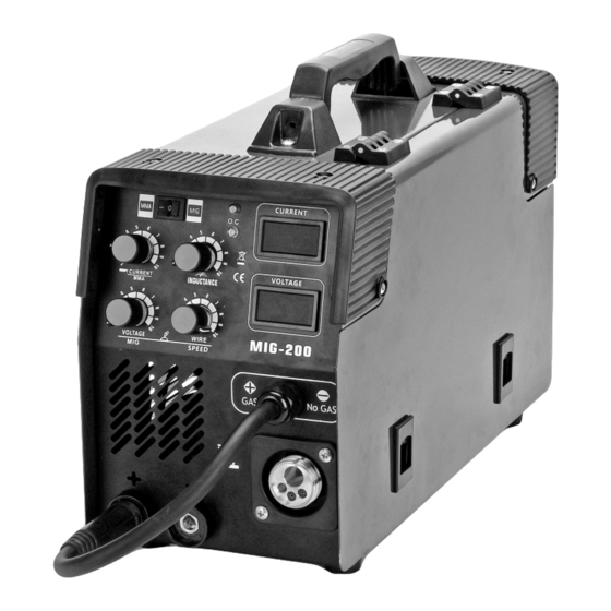
MIG-DS Series Panel Introduction
Panel Overview and Controls
Introduces panel elements like voltage/current displays, parameter adjustment, and mode selection.
Connection and Polarity Setup
Details polarity conversion, gas connections, and power cable setup.
Operation and Error Codes
Common Operation and Error Codes
Lists and explains codes related to voltage, current, feeder speed, and protection.
Function Code Configuration
Details function codes for inductance, torch control, hot start, and arc force settings.
MIG-S2 Series Panel Introduction
Panel Controls and Indicators
Identifies panel elements like alarms, displays, mode switches, and adjustments.
Connection and Power Setup
Details polarity connectors, gas connection, power switch, and cable connections.
Function Descriptions
Indicators and Displays
Explains Over-Heat Alarm, Power Indicator, and welding current/voltage displays.
Welding Mode and Parameter Controls
Covers mode switching, wire inching, burnback, voltage, and wire speed adjustments.
Connections and Components
Details polarity connectors, torch, gas hose, power cable, and ground nut.
Installation Procedures
General Installation Guidelines
Covers voltage compensation, cable length, and intake protection.
Gas Welding (Solid Wire) Setup
Details connecting gas bottle, earth cable, wire spool, and torch setup.
Operation Guidelines
General Operation Steps
Outlines powering on, adjusting flow, selecting tips, and tuning switches.
Gasless Welding (Flux-cored Wire) Setup
Covers earth cable, wire spool, wire slot, and torch setup for gasless welding.
Notes and Preventive Measures
Environmental Considerations
Specifies operating environment conditions like dryness, temperature, and air quality.
Safety Norms and Protection
Covers ventilation, duty cycle limits, voltage protection, grounding, and overheat protection.
Common Welding Questions
Arc Striking and Output Issues
Discusses problems with arc initiation, output current, and current stabilization.
Welding Gap and Material Preparation
Covers issues related to welding gap, gas supply, and material surface contamination.
Maintenance Guidelines
Cleaning and Circuit Checks
Outlines dust removal, circuit inspection, and connector tightening.
Storage and Component Care
Advises on avoiding water, proper storage, and polishing components.
Fault Diagnosis and Resolution
Power Indicator Faults
Lists reasons for the power indicator being off or fan not working with no output.
Indicator and Output Faults
Covers faults where the indicator is lit but there is no output or abnormal indicators.
Daily Checking Procedures
Welding Power Supply Checks
Details checks for control panel, cooling fan, power part, and periphery.
Welding Torch Component Checks
Covers checks for torch loophole, electric hole, wire sending tube, and gas bypass.
Daily Checks (Wire Feeder and Cable)
Wire Feeder Component Checks
Outlines checks for pressing arm, wire lead tube, wire wheel, and pressure wheel.
Cable Integrity Checks
Covers checks for torch cable, output cable, input cable, and earth cable.
Need help?
Do you have a question about the MIG-270 and is the answer not in the manual?
Questions and answers