Table of Contents
Advertisement
Quick Links
Full Digital Heavy Duty IGBT CO
/MAG/MMA Carrier
2
Intelligent Multifunctional Inverter Welder
User Manual
Version: V1.4
No.: R33010063
Shenzhen Megmeet Electric Co., Ltd. provides comprehensive technical support for customers,
covering but not limited to, CAN communication, welder network monitors, robot collaboration,
welding process database software upgrade, and after-sale service. Users can contact the nearest
Megmeet's offices or customer service centers, or directly contact Megmeet headquarters.
Shenzhen Megmeet Electric Co., Ltd.
All rights reserved. The content may subject to change without notice.
Shenzhen Megmeet Electric Co., Ltd.
Address: 5th Floor Block B, Ziguang Information Harbor, Langshan Road, Shenzhen, 518057,
China
Zip code: 518057
Website: www.megmeet.com
Customer service hotline: 4006662163
Email: Welder.4S@megmeet.com
Advertisement
Table of Contents

Related Manuals for IGBT CO2


Summary of Contents for IGBT CO2
- Page 1 Full Digital Heavy Duty IGBT CO /MAG/MMA Carrier Intelligent Multifunctional Inverter Welder User Manual Version: V1.4 No.: R33010063 Shenzhen Megmeet Electric Co., Ltd. provides comprehensive technical support for customers, covering but not limited to, CAN communication, welder network monitors, robot collaboration, welding process database software upgrade, and after-sale service.
- Page 2 Preface Thank you for choosing Megmeet's full digital heavy duty IGBT CO2/MAG/MMA carrier intelligent multifunctional inverter welder (hereinafter referred to as the welder). This document covers the precautions on installation and cabling, parameter setup, troubleshooting, and daily maintenance. To ensure that the welder is installed and operated properly and can achieve its optimal performance, read this user manual before installation.
- Page 3 Safety Precautions Safe Definition Danger Follow instructions to perform operations. Failing to do so may result in death or serious injuries. Note Follow instructions to perform operations. Failing to do so may result in medium or slight injuries or property damages. ●...
- Page 4 Danger ● Perform maintenance 5 minutes only after the power supply is disconnected, the power indicator is completely off, and the voltage of the positive and negative bus bars is lower than 36 V; failing to do so may result in electric shock. ●...
- Page 5 Danger cables with damages. ● Do not remove the housing or cover plates when the welder is in use. ● Wear insulation gloves with good insulation performance and without damages. ● Take safety measures when doing tasks at high places. ●...
- Page 6 Note ● Fix the casters to prevent the welder from sliding. ● To prevent electromagnetic hazards, implement electromagnetic shielding for cables and welding sites. ● The slope of the surface must be less than 15 degrees to prevent the welder from falling down. ●...
-
Page 7: Table Of Contents
Contents Chapter 1 Product Overview ............................. 1 1.1 Model Description ............................1 1.2 Technical Specifications ..........................1 1.3 External Dimensions and Gross Weight ......................4 1.4 System Components and Configuration ......................5 1.4.1 System Components ........................... 5 1.4.2 Configuration ............................6 1.5 System Features ............................ - Page 8 3.4.4 Welding with Ending Arc ........................38 3.4.5 Welding with Repeated Ending Arc .....................40 3.4.6 Synergic/Manual ..........................41 3.4.7 Arc Dynamic ............................42 3.4.8 Detect Gas ............................43 3.4.9 Wire Inching ............................44 3.4.10 SAVE and LOAD ..........................45 3.4.11 Lock..............................47 3.4.12 Internal Menu ...........................56 3.4.13 Welder Network Monitors .........................57 3.5 Welding Electrode ............................57 3.6 Intelligent Function Description ........................57 3.6.1 Energy Conservation Function of the Fan....................57...
-
Page 9: Chapter 1 Product Overview
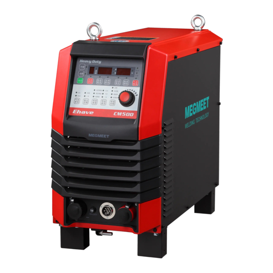
This chapter describes the model, appearance, dimensions, system components, system configuration, technical specifications, and system features of the Ehave full digital heavy duty IGBT CO2/MAG/MMA carrier intelligent multifunctional inverter welder. 1.1 Model Description Figure 1-1 describes the welder model code format. - Page 10 Sets welding voltage and current Main control values, and displays welding voltage values, and displays welding LED screen functions and current values and error codes. voltage and current values and error codes. Ehave Series Full Digital IGBT CO /MAG/MMA Multifunctional Inverter Welder User Manual...
- Page 11 They are used to confirm, save, load, ENTER and lock welding parameters. , and They are used to confirm, save, LOAD load, and lock welding parameters. SAVE buttons Ehave Series Full Digital IGBT CO /MAG/MMA Multifunctional Inverter Welder User Manual...
-
Page 12: External Dimensions And Gross Weight
Ehave CM250/350 Ehave CM500 Ehave CM500H Welder 49 kg 52 kg 55 kg Wire feeder 10 kg 10 kg 10 kg Welding torch 3 kg 3.5 kg 3.5 kg Ehave Series Full Digital IGBT CO /MAG/MMA Multifunctional Inverter Welder User Manual... -
Page 13: System Components And Configuration
Welding power cable Wire feeder on the wire feeder side Control power cable on the wire feeder side Welding power Workpiece cable on the workpiece side Figure 1-3 System components Ehave Series Full Digital IGBT CO /MAG/MMA Multifunctional Inverter Welder User Manual... -
Page 14: Configuration
Adjusts the welding mode. For details, see the operation Control panel description. 1.4.2 Configuration Table 1-3, Table 1-4, and Table 1-5 show the configuration lists of welders. Ehave Series Full Digital IGBT CO /MAG/MMA Multifunctional Inverter Welder User Manual... - Page 15 Either type of welding torch is compliant with provided. By default, a welding torch Japanese standards compliant with Japanese standards is provided. Welding torch MB 36 KD/N36 compliant with European standards Ehave Series Full Digital IGBT CO /MAG/MMA Multifunctional Inverter Welder User Manual...
- Page 16 Analog Standard communication cable Wire guide nozzle for Optional the robotic wire feeder Nut for the robotic wire Optional feeder Ehave Series Full Digital IGBT CO /MAG/MMA Multifunctional Inverter Welder User Manual...
-
Page 17: System Features
100% with the load lighter than 193 A. The duty cycle of Ehave CM350/350AR is 100% with the load lighter than 271 A. The duty cycle of Ehave CM500/500AR is 100% with the load lighter than 390 A. Ehave Series Full Digital IGBT CO /MAG/MMA Multifunctional Inverter Welder User Manual... - Page 18 If this welder is used along with other parts such as welding torches, the lowest duty cycle of the parts must be applied to the entire set of device. Ehave Series Full Digital IGBT CO /MAG/MMA Multifunctional Inverter Welder User Manual...
- Page 19 Ehave CM500/500H is used as an example. Figure 1-7 Schematic diagram of the constant–voltage welding power source (39 V) Figure 1-8 Schematic diagram of the constant-current welding power source (150 A) Ehave Series Full Digital IGBT CO /MAG/MMA Multifunctional Inverter Welder User Manual...
-
Page 20: Chapter 2 Installation And Cabling
3. If a crane is required to move the welder, use hoist rings and two lifting belts, and the included angle of each lifting belt and the vertical direction must be less than 15 degrees. See Figure 2-1. Ehave Series Full Digital IGBT CO /MAG/MMA Multifunctional Inverter Welder User Manual... -
Page 21: Power Supply Specifications
Output on the welder 35 mm or greater 50 mm or greater Power cable side Housing ≥ power supply cable ≥ power supply cable grounding cable Ehave Series Full Digital IGBT CO /MAG/MMA Multifunctional Inverter Welder User Manual... -
Page 22: Open-Package Inspection
7-core control cable. 2.5.1 Packing List for the Cable Bundle Component Box Table 2-3 and Table 2-4 provide packing lists of cable bundle component boxes. Ehave Series Full Digital IGBT CO /MAG/MMA Multifunctional Inverter Welder User Manual... -
Page 23: Cable Bundle Preparation Description
, while if the power cable length ranges from 30 m to 50 m, the default cross-sectional area is 70 mm . Use the bare crimp terminals matching the cable. Ehave Series Full Digital IGBT CO /MAG/MMA Multifunctional Inverter Welder User Manual... -
Page 24: Electric Connections
6. Running water pipes and reinforcing bars of houses may not be adequately grounded. Do not connect grounding cables to them. 7. Each welder is equipped with one air circuit breaker or fused switch. Ehave Series Full Digital IGBT CO /MAG/MMA Multifunctional Inverter Welder User Manual... -
Page 25: Welder Output Cables
1. Connect the 7-core aviation plug of the cable bundle to the 7-core jack on the welder. 2. Rotate the screw cap of the plug clockwise to fasten it. 3. Figure 2-4 shows the cable connections. Ehave Series Full Digital IGBT CO /MAG/MMA Multifunctional Inverter Welder User Manual... -
Page 26: Connecting The Gas Cylinder
The procedure for connecting to the gas cylinder is as follows: 1. Use installation nuts to mount the electrically-heated CO2 regulator (see Figure 2-5) to the gas outlet of the gas cylinder, and fasten the regulator. 2. Connect one end of the gas tube to the gas tube connector of the regulator and use a fastener to fasten the connection. -
Page 27: Connecting The Wire Feeder
The procedure for connecting the wire feeder is as follows: 1. Fix the 7-core control cable, gas tube, and positive output welding cable with the clamp at the rear of the wire feeder. See Figure 2-7. Ehave Series Full Digital IGBT CO /MAG/MMA Multifunctional Inverter Welder User Manual... -
Page 28: Connecting The Welding Torch
After cabling for the wire feeder is complete, refer to the wire feeder user manual and welding torch user manual to connect the welding torch to the wire feeder. Figure 2-9 shows the connection. Ehave Series Full Digital IGBT CO /MAG/MMA Multifunctional Inverter Welder User Manual... -
Page 29: Connecting The Welding Power Cable (Grounding Cable) On The Workpiece Side
4. Install the input terminal cover. 5. Connect the other end of the input power cable to the output terminal of the power switch of the distribution box. Ehave Series Full Digital IGBT CO /MAG/MMA Multifunctional Inverter Welder User Manual... -
Page 30: Welding Preparation
/MAG welding mask, see Table 2-5. Table 2-5 Selection of light filters for the GB-T3609-1994 welding mask Shading Numeral Arc Welding and Cutting Task Protection against sidelight and stray light Ehave Series Full Digital IGBT CO /MAG/MMA Multifunctional Inverter Welder User Manual... -
Page 31: Installing The Welding Wire
1. Turn on the switch of the distribution box and connect the three-phase 380 V power supply. 2. Turn the switch of the welder to the ON position. See Figure 1-4. Ehave Series Full Digital IGBT CO /MAG/MMA Multifunctional Inverter Welder User Manual... -
Page 32: Adjusting The Gas Flow
You can also use the wire inching button on the remote control box of the wire feeder to inch wire and use the current adjusting knob to change the wire inching speed. Ehave Series Full Digital IGBT CO /MAG/MMA Multifunctional Inverter Welder User Manual... -
Page 33: Welding Conditions
If high welding quality is required, you are recommended to determine the optimal welding process parameters through tests. The wire diameter adopted for the actual welder shall prevail. Ehave Series Full Digital IGBT CO /MAG/MMA Multifunctional Inverter Welder User Manual... - Page 34 4 - 6 Internal 1 32 - 35 45 - 50 20 - 25 butt welding External 380 - 36 - 39 35 - 40 20 - 25 Ehave Series Full Digital IGBT CO /MAG/MMA Multifunctional Inverter Welder User Manual...
- Page 35 21 - 23 40 - 45 15 - 20 45 5 - 5.5 200 - 250 24 - 26 40 - 50 10 - 15 10 - 20 Ehave Series Full Digital IGBT CO /MAG/MMA Multifunctional Inverter Welder User Manual...
- Page 36 1.0, 1.2 115 - 125 19.5 - 20 50 - 60 10 - 15 1.0, 1.2 130 - 140 19.5 - 21 50 - 60 10 - 15 Ehave Series Full Digital IGBT CO /MAG/MMA Multifunctional Inverter Welder User Manual...
- Page 37 Titania 250 - 270 27 - 29 68 - 72 310 - 330 30 - 32 48 - 52 340 - 360 32 - 34 33 - 37 Ehave Series Full Digital IGBT CO /MAG/MMA Multifunctional Inverter Welder User Manual...
-
Page 38: Post-Welding Tasks
Note Do not turn off the power supply of the welder until 3 to 5 minutes after welding is complete. This facilitates internal cooling of the welder. Ehave Series Full Digital IGBT CO /MAG/MMA Multifunctional Inverter Welder User Manual... -
Page 39: Chapter 3 Welder Operation Description
The preceding figure shows the front control panel of Ehave CM500, which is the same as those of Ehave CM500H/500AR. On the front control panels of Ehave CM250/350/350AR, the wire diameters are 0.8, 1.0, and 1.2. Ehave Series Full Digital IGBT CO /MAG/MMA Multifunctional Inverter Welder User Manual... - Page 40 Selects the diameter of the welding wire. If Wire type is set to Flux-cored wire, the system allows only the wire diameters 1.2 mm and 1.6 mm. Welding control Selects the welding control mode. Ehave Series Full Digital IGBT CO /MAG/MMA Multifunctional Inverter Welder User Manual...
-
Page 41: Remote Control Box Of The Wire Feeder
Rotating a knob counter-clockwise reduces a value, while rotating a knob clockwise increases a value. Figure 3-3 shows the positions of buttons and knobs. Ehave Series Full Digital IGBT CO /MAG/MMA Multifunctional Inverter Welder User Manual... -
Page 42: Screens And Led Indicators
The middle screen displays a current value, a spot welding time, or a code. When the current indicator A turns on, it displays a current value. When the spot welding time indicator S turns Ehave Series Full Digital IGBT CO /MAG/MMA Multifunctional Inverter Welder User Manual... -
Page 43: Control Panel Functions
1. Use the current and voltage adjusting knobs on the wire feeder to set the welding current and voltage. 2. Press the Welding control button and switch to the spot welding mode. Ehave Series Full Digital IGBT CO /MAG/MMA Multifunctional Inverter Welder User Manual... - Page 44 Turn off the power Turn on the power switch of the switch of the welding torch. welding torch. Figure 3-6 Schematic diagram of spot welding Figure 3-7 shows the welding logic. Ehave Series Full Digital IGBT CO /MAG/MMA Multifunctional Inverter Welder User Manual...
-
Page 45: Welding Without Ending Arc
When the switch of the welding torch is turned to ON, an arc is generated. When the switch of the welding torch is turned to OFF, welding stops. See Figure 3-6. Ehave Series Full Digital IGBT CO /MAG/MMA Multifunctional Inverter Welder User Manual... -
Page 46: Welding With Ending Arc
4. Figure 3-10 shows the control panel where the parameters have been set. Ehave Series Full Digital IGBT CO /MAG/MMA Multifunctional Inverter Welder User Manual... - Page 47 Welding voltage Wire inching speed Welding current Ending Delayed gas Send gas Starting Weld sending before Wire sticking welding prevention Figure 3-12 Logic for welding with ending arc Ehave Series Full Digital IGBT CO /MAG/MMA Multifunctional Inverter Welder User Manual...
-
Page 48: Welding With Repeated Ending Arc
2 seconds, welding with repeated ending arc is performed again. This procedure repeats when you repeat the preceding operation. Figure 3-14 shows the welding procedure. Ehave Series Full Digital IGBT CO /MAG/MMA Multifunctional Inverter Welder User Manual... -
Page 49: Synergic/Manual
30 V. 2. Press the Synergic button on the control panel and perform welding in synergic mode. Ehave Series Full Digital IGBT CO /MAG/MMA Multifunctional Inverter Welder User Manual... -
Page 50: Arc Dynamic
Arc hardness can be adjust within the range of -9 to +9. Rotating the knob clockwise increases the hardness, while rotating the knob counter-clockwise reduces the hardness. Table 3-2 and Figure 3-17 describe the arc dynamic. Ehave Series Full Digital IGBT CO /MAG/MMA Multifunctional Inverter Welder User Manual... -
Page 51: Detect Gas
Wire Welding Gas type control type diameter control Figure 3-18 Setting gas detection Note: If you do not manually stop gas detection, it stops automatically after 30 seconds. Ehave Series Full Digital IGBT CO /MAG/MMA Multifunctional Inverter Welder User Manual... -
Page 52: Wire Inching
2. Release the Wire Inching button and wire inching stops. Ehave Series Full Digital IGBT CO /MAG/MMA Multifunctional Inverter Welder User Manual... -
Page 53: Save And Load
3. Select the welding parameter settings to be saved. Figure 3-18 shows the control panel where the parameter settings are saved. 4. Press the ENTER button to save the parameter settings. After the parameter settings are saved, the indicators turn off. Ehave Series Full Digital IGBT CO /MAG/MMA Multifunctional Inverter Welder User Manual... - Page 54 3. When the factory settings of the welder are restored, the saved parameter settings are not deleted. LOAD The procedure is as follows: 1. Press the LOAD button. The Job No. indicator turns on and the LOAD indicator flashes. Ehave Series Full Digital IGBT CO /MAG/MMA Multifunctional Inverter Welder User Manual...
-
Page 55: Lock
In common lock mode, all the buttons and knobs (expect the SAVE , LOAD ENTER , Inch wire , and Detect gas buttons) on the control panel of the welder cannot be used. Ehave Series Full Digital IGBT CO /MAG/MMA Multifunctional Inverter Welder User Manual... - Page 56 The common lock function is disabled, and the parameters are unlocked. See Figure 3-24. Figure 3-24 Disabling the common lock Figure 3-25 shows the procedure for using the common lock. Ehave Series Full Digital IGBT CO /MAG/MMA Multifunctional Inverter Welder User Manual...
- Page 57 -, use the knob on the control panel to enter the original 6-character password according to the flashing indication on the screens and press the LOAD button. See Figure 3-26. Ehave Series Full Digital IGBT CO /MAG/MMA Multifunctional Inverter Welder User Manual...
- Page 58 6. On the UI for confirming the new password, the first screen displays 2, and the middle and right screens display -. See Figure 3-31. Use the knob on the control panel to enter the 6-character new password and press the LOAD button. Ehave Series Full Digital IGBT CO /MAG/MMA Multifunctional Inverter Welder User Manual...
- Page 59 UI for confirming a new password, the common lock UI is displayed after restarting is complete and the original password is not changed. Figure 3-34 shows the procedure for changing a password. Ehave Series Full Digital IGBT CO /MAG/MMA Multifunctional Inverter Welder User Manual...
- Page 60 When the first screen displays o, the middle and right screens display -, use the knob on the control panel to enter the 6-character lock password according to the flashing indication on the screens and press the LOAD button. Ehave Series Full Digital IGBT CO /MAG/MMA Multifunctional Inverter Welder User Manual...
- Page 61 The current and voltage adjustment ranges are locked. In the state, you can perform welding and adjust the current and voltage within the specified ranges. Flashing Channel indicator Figure 3-38 UI indicating that welding parameter adjustment ranges are locked Ehave Series Full Digital IGBT CO /MAG/MMA Multifunctional Inverter Welder User Manual...
- Page 62 If you press and hold the ENTER button to unlock welding parameter adjustment ranges, the UI for entering the lock password is displayed. Enter the lock password to disable the function. Ehave Series Full Digital IGBT CO /MAG/MMA Multifunctional Inverter Welder User Manual...
- Page 63 Enter the lock password. Correct State where the welding parameter adjustment ranges are unlocked (The password lock is disabled.) Figure 3-39 Procedure for locking the welding parameter adjustment ranges Ehave Series Full Digital IGBT CO /MAG/MMA Multifunctional Inverter Welder User Manual...
-
Page 64: Internal Menu
32PP Hot startup current 50 A 30 A 33PP Thrust current Reverse switch for Factory setting: arc starting success of welding robot Figure 3-40 Internal menu description Ehave Series Full Digital IGBT CO /MAG/MMA Multifunctional Inverter Welder User Manual... -
Page 65: Welder Network Monitors
CM500/500H/500AR, it rotates at a low speed when the welding current is lower than 300 A, and rotates at a high speed when the welding current is higher than 300 A. It stops working 10 minutes after welding is ended. Ehave Series Full Digital IGBT CO /MAG/MMA Multifunctional Inverter Welder User Manual... -
Page 66: Safety Protection Function For The Welding Torch
Analog signal provided by the welder to the Note 4 robot to indicate the actual welding current value. Common grounding for Common grounding for the I/O signals of pins Ehave Series Full Digital IGBT CO /MAG/MMA Multifunctional Inverter Welder User Manual... - Page 67 I/O signals are transmitted at a high level, arc is not started. The loading capability of the I/O signal ranges from 0 mA to 15 mA. Ehave Series Full Digital IGBT CO /MAG/MMA Multifunctional Inverter Welder User Manual...
- Page 68 Vref is Vav = 0.303 Vref - 3.636. See Figure 3-45. That is, when the actual preset voltage is 30 V, the preset voltage signal value is 5.455 V. Vref Figure 3-45 Relationship between Vav and Vref Ehave Series Full Digital IGBT CO /MAG/MMA Multifunctional Inverter Welder User Manual...
- Page 69 30 V, the welding voltage signal value is 4.55 V. Vvolt 10.55V 0.55V Vreal Figure 3-47 Relationship between Vvolt and Vreal Direction of connector A View of connecter A Figure 3-48 Pin numbers of the DB15 connector Ehave Series Full Digital IGBT CO /MAG/MMA Multifunctional Inverter Welder User Manual...
-
Page 70: Restoring Factory Settings
1. When the factory settings of the welder are restored, the parameters saved to channels are not deleted. 2. When the factory settings of the welder are restored, the lock password is not deleted. Ehave Series Full Digital IGBT CO /MAG/MMA Multifunctional Inverter Welder User Manual... -
Page 71: Chapter 4 Maintenance
General welder is operational is normal. internal inspection on the welder. Check whether a peculiar smell or unexpected vibration or noises are detected when the welder is operational. Ehave Series Full Digital IGBT CO /MAG/MMA Multifunctional Inverter Welder User Manual... -
Page 72: Regularly Inspection
PCBs of the welder. 2. Do not use the solution other than neutral detergents for household use to clean the plastic parts. Ehave Series Full Digital IGBT CO /MAG/MMA Multifunctional Inverter Welder User Manual... - Page 73 Voltage-Resistance Test and Insulation Test The tests can performed only by Megmeet's after-sale service personnel or professional personnel with knowledge on electric devices and welders. Ehave Series Full Digital IGBT CO /MAG/MMA Multifunctional Inverter Welder User Manual...
-
Page 74: Troubleshooting
4.3.2 Welder Error Codes and Solutions Figure 4-1 shows the screens and indicators. Three nixie tubes in Three nixie tubes in the middle screen the right screen Figure 4-1 Schematic diagram of screens Ehave Series Full Digital IGBT CO /MAG/MMA Multifunctional Inverter Welder User Manual... - Page 75 Check the buttons corresponding to the numbers A button does not 1 - 14 Button error (displayed on the right screen) rebound after being shown in Figure 3-1. pressed. Ehave Series Full Digital IGBT CO /MAG/MMA Multifunctional Inverter Welder User Manual...
- Page 76 Verify that the input voltage detection cable is broken. detection cable is normal. PCB not Purchase the PCB certified by None The PCB is not certified. registered the Megmeet. Ehave Series Full Digital IGBT CO /MAG/MMA Multifunctional Inverter Welder User Manual...
-
Page 77: Rectifying Welder Faults And Welding Process Issues
Excessive roll-up or bending occurs. The tip and wire liner do not match the welding wire. Welding torch The tip or wire liner is worn out, blocked, or deformed. Ehave Series Full Digital IGBT CO /MAG/MMA Multifunctional Inverter Welder User Manual... -
Page 78: After-Sale Service
The warranty does not cover a product damage caused when the product is not used properly by the user. However, such damage can be handled in the repair process. Ehave Series Full Digital IGBT CO /MAG/MMA Multifunctional Inverter Welder User Manual... -
Page 79: Appendix I Technical Specifications
: 100%; MAG: Ar 80% + CO Spot welding time 0.1 - 10 0.1 - 10 Dimensions (L x W x H) 667.5 x 300 x 564 667.5 x 300 x 564 Weight Ehave Series Full Digital IGBT CO /MAG/MMA Multifunctional Inverter Welder User Manual... - Page 80 50 or greater power cable on the welding material side Electrically-heated CO GH-257-36/394C-25L-36 GH-257-36/394C-25L-36 regulator Gas tube 3 m - 30 m (optional) 3 m - 50 m (optional) Ehave Series Full Digital IGBT CO /MAG/MMA Multifunctional Inverter Welder User Manual...
-
Page 81: Appendix Ii Electric Connections Of Ehave Cm250/350
1 2 3 4 380V Output EMC board 108V WPCM131 WPCM1315M3 DC fan board WPCM1315M2 Wire feeder control board (DSP) NTC- NTC-0+ NTC-S 8.5V WPCM1315U1 Button display board (MCU) Ehave Series Full Digital IGBT CO /MAG/MMA Multifunctional Inverter Welder User Manual... -
Page 82: Appendix Iii Electric Connections Of Ehave Cm500/500H
1 2 3 4 WPCM1315A3 Output EMC board 108V WPCM1315M3 DC fan board WPCM1315M2 Wire feeder control board (DSP) NTC- NTC-0+ NTC-S 380V WPCM1315 WPCM1315U1 8.5V Button display board (MCU) Ehave Series Full Digital IGBT CO /MAG/MMA Multifunctional Inverter Welder User Manual... -
Page 83: Appendix Iv Components
Fuse base 7-core aviation plug Positive output terminal Diode Output absorption board Inductor Cable terminal block Hex key Caster Plastic panel ZA chassis without load Figure 1 Components Ehave Series Full Digital IGBT CO /MAG/MMA Multifunctional Inverter Welder User Manual... -
Page 84: Appendix V Detailed Component List
Cable terminal block 30040910 30040910 R34020011 R34020011 Hex key R29120011 R29120011 Caster 4, Optional R29120012 4, Optional R29120012 Plastic panel R29060228 R29060228 ZA chassis without R29140023 R29140001 load Ehave Series Full Digital IGBT CO /MAG/MMA Multifunctional Inverter Welder User Manual... - Page 85 Shenzhen Megmeet Electric Co., Ltd. Shenzhen Megmeet Electric Co., Ltd. Welder Warranty Card Welder Warranty Card Company: Company: Address: Address: Zip code: Contact person: Zip code: Contact person: Tel: Fax: Tel: Fax: Machine model: Machine model: Power: Machine ID: Power: Machine ID: Contract ID: Purchase date:...
- Page 86 User Notice User Notice 1. The warranty covers only the welder. 1. The warranty covers only the welder. 2. The warranty period is 12 months. Welder faults or damages caused during 2. The warranty period is 12 months. Welder faults or damages caused during normal usage within the period will be fixed by Megmeet free of charge.