Table of Contents
Advertisement
Quick Links
Advertisement
Table of Contents

Related Manuals for IGBT MIG-200Tec


Summary of Contents for IGBT MIG-200Tec
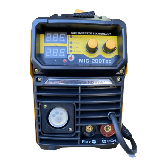
- Page 1 IGBT INVERTER MIG/MMA WELDER USER ′ S MANUAL IGBT MODEL:MIG-200Tec - 1 -...
-
Page 2: Safety Caution
Safety Caution! On the process of welding, there will be any possibility of injury, so please take protection into consideration during operation. More details please review the Operator Safety Guide, which complies with the preventive requirements of the manufacturer Electric shock——may lead to death ! ! ·... -
Page 3: About The Machine
The development of inverter gas-shielded welding equipment profits from the development of the inverter power supply theory and components. Inverter gas-shielded welding power source utilizes high-power component IGBT to transfer 50/60HZ frequency up to 100KHZ, then reduce the voltage and commutate, and output high-power voltage via PWM technology. - Page 4 PARAMETERS MIG-200Tec Model No 1 Phase 220V15% Input Voltage(V) Frequency(Hz) Rated Input Current(A) 28.5 Input Capacity (KVA) MIG-6.1 / MMA-7.2 Output Current (A) 40-200 No-load Voltage (V) Duty Cycle(%)...
-
Page 5: Set Up For Welding
Installment The welding equipment is equipped with power voltage compensation set. When power voltage changes between±15% of rated voltage, it still works normally. When using long cable, in order to minimize the reduce of voltage, big section cable is suggested. If the cable is too long, it will affect the performance of arcing and other system function, so stated length is suggested. - Page 6 matched with the wheel fixer. 4) Choose wire slot according to wire size. 5) Loosen the screw of wire-pressing wheel, put the wire into slot via wire-lead tube, tune the Wire-pressing wheel to fix wire from gliding,but pressure should be suitable in case the wire distorts and affects wire sending.
-
Page 7: Operation
Operation 1、 Put the air switch to “ON” position, open the valve of CO2 cylinder and adjust the flow. 2、 Adjust the wire diameter of the wire machine to rated number according to wire diameter. 3、 Choose torch loophole span based on wire diameter. 4、... -
Page 8: Notes Or Preventive Measures
NOTES OR PREVENTIVE MEASURES - 8 -... - Page 9 1、Environment 1) The machine can perform in environment where conditions are dry with a dampness lever of max 90%. 2) Ambient temperature is between 10 to 40 degrees centigrade. 3) Avoid welding in sunshine or dripaings. 4) Do not use the machine in environment where condition is polluted with conductive dust on the air or corrosiveness gas on the air.
- Page 10 4)There is a grounding screw behind welding machine, there is grounding marker on it Mantle must be grounded reliable with cable which section is over 6 square millimeter I order to prevent from static electricity and leaking. 5)If welding time is exceeded duty cycle limited, welding machine will stop working for protection.
- Page 11 CAUTION: Before Maintenance and checking, power must be turned off, and before Opening the housing, make sure the power plug is pulled off. 1、 Remove dust by dry and clean compressed air regularly, if welding machine is operating in environment where is polluted with smokes and pollution air, the machine need remove dust every day.
- Page 12 - 12 -...
- Page 13 No Item No Item Plastic Handle IGBT Tube Hinge Drive Transformer Outer Body Shell Fast-Recovery Diode Front Plastic Panel Heat Sink Rotary Knob Insulated Flange Front Panel Wire Feeder Digital Meter Coil Shaft Cable Connector Foot Pad Main PC Board...
- Page 14 CHECK FAULT Notes: If user wants to operate machine as following, the operator must be a personnel in a specific field of electricity and safety and hold the relevant certification that proves their ability and knowledge. Before maintenance, contact with our sale agent for authorization is suggested. Faults Resolvable Method 1、Make sure air switch is closed.
-
Page 15: Check Faults
(1) If abnormal indicator is still lit, some of IGBT is damaged on the main board, find out and replace it with same model. (2) If abnormal indicator is not lit,: Maybe transformer is damaged, measure inductance volume and Q volume of main transformer by inductance bridge. -
Page 16: Earlier Checking Diagram For The Abnormal
EARLIER CHECKING DIAGRAM FOR THE ABNORMAL The abnormal Items to be checked Power supply 1、connected or not 〇 〇 〇 〇 〇 〇 2、Fuse broken (input 3、Connector loosen protectiv e set) 1、 Broken or not Input 2、 Connector 〇 〇 〇... -
Page 17: Daily Checking
1、 Wheel leading tube not match 2、 Wheel broken, Wire slot blocked or sending 〇 〇 〇 〇 〇 lack equipme 3、 Over pressing or loosen, powder store entrance of SUS tube DAILY CHECKING WELDING POWER SUPPLY Position Checking keys Remarks 1.Switch condition of operation, Control... -
Page 18: Welding Torch
WELDING TORCH Position Checking keys Remarks 1.If installment fixed, the front Reason for air hole. distorted Loophole Reason for burning the torch. (Can use the splash-proof 2.Attach splash or not. material) Reason of torch screw thread 1.If installment fixed damage Electric hole 2.damage of its head and hole... - Page 19 WIRE SENDING MACHINE Position Checking keys Remarks 1.If put the arm to the suitable indicating level. Pressing Lead to unstable arc and wire (notes: not to damage wire less sending. than Ф1.0mm ) 1.If powder or residue store up Clean the residue and check the in the mouth of the tube.
- Page 20 CABLE Position Checking keys Remarks 1.If torch cable over bended. 1. Cause poor wire sending Torch 2.If the metal connecting point of 2. Unstable arc if cable over cable mobile plug loosen bended. Wearing-out cable insulated material. 2.Cable connecting head naked Output (insulation damage), or loosen cable...
Need help?
Do you have a question about the MIG-200Tec and is the answer not in the manual?
Questions and answers