Table of Contents
Advertisement
Quick Links
Advertisement
Table of Contents

Related Manuals for AG Neovo QM-55


Summary of Contents for AG Neovo QM-55
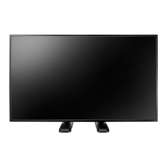
- Page 1 QM-43 & QM-55 LED-Backlit Display User Manual displays.agneovo.com...
-
Page 2: Table Of Contents
TABLE OF CONTENTS SAFETY INFORMATION ................1 Federal Communications Commission (FCC) Notice (U.S. Only) ............1 CE ................................1 Polish Center for Testing and Certification Notice ..................1 Electric, Magnetic and Electromagnetic Fields (“EMF”) ................2 Information for U.K. only ........................... 3 North Europe (Nordic Countries) Information ................... - Page 3 TABLE OF CONTENTS 2.4 Connecting Audio Equipment ......................30 2.4.1 Connecting an External Audio Device ..................30 2.5 Using the Card Reader ........................31 2.6 Connecting Multiple Displays in a Daisy-chain Configuration ............32 2.6.1 Display Control Connection ..................... 32 2.7 IR Connection .............................
-
Page 4: Safety Information
SAFETY INFORMATION Fe d e r a l Co m m u n ic a t io n s Co m m is s io n ( FCC) No t ic e ( U.S. On l y ) This equipment has been tested and found to comply with the limits for a Class A digital device, pursuant to part 15 of the FCC Rules. -
Page 5: Electric, Magnetic And Electromagnetic Fields ("Emf")
PRODUCT DESCRIPTION El e c t r ic , Ma g n e t ic a n d El e c t r o m a g n e t ic Fie l d s ( “ E MF” ) •... -
Page 6: Information For U.k. Only
PRODUCT DESCRIPTION In f o r m a t io n f o r U.K. o n l y WARNING - THIS APPLIANCE MUST BE EARTHED. Important: This apparatus is supplied with an approved moulded 13A plug. To change a fuse in this type of plug proceed as follows: Remove fuse cover and fuse. -
Page 7: North Europe (Nordic Countries) Information
PRODUCT DESCRIPTION Ho w t o c o n n e c t a p l u g The wires in the mains lead are coloured in accordance with the following code: BLUE - “NEUTRAL” (“N”) BROWN - “LIVE” (“L”) GREEN &... -
Page 8: End-Of-Life Disposal
PRODUCT DESCRIPTION En d - o f - Lif e Dis p o s a l our ne Pu lic nfor ation Display contains aterials that can e recycled and reused. Speciali ed co panies can recycle your product to increase the a ount of reusa le aterials and to ini i e the a ount to be disposed of. -
Page 9: Turkey Rohs
PRODUCT DESCRIPTION Ba t t e r ie s For EU: The crossed-out wheeled bin implies that used batteries should not be put to the general household waste! There is a separate collection system for used batteries, to allow proper treatment and recycling in accordance with legislation. Please contact your local authority for details on the collection and recycling schemes. -
Page 10: Precautions
PRECAUTIONS CAUTION RISK OF ELECTRIC SHOCK DO NOT OPEN Sy m b o l s u s e d in t h is m a n u a l This icon indicates the existence of a potential haz a rd that could result in personal injury or damage to the product. -
Page 11: Cautions When Using
PRODUCT DESCRIPTION Ca u t io n s W h e n Us in g • Use only the power cord supplied with the LCD display. • The power outlet should be installed near the LCD display and W a r n in g : be easily accessible. -
Page 12: Notice For The Lcd Display
PRODUCT DESCRIPTION No t ic e f o r t h e LCD Dis p l a y • In order to maintain the stable luminous performance, it is recommended to use low brightness setting. • Due to the lifespan of the lamp, it is normal that the brightness quality of the LCD display may decrease with time. -
Page 13: Chapter 1: Product Description
AAA batteries. QM-43 For all other regions, apply a Quick Start Guide power cord that conforms to QM-43 LED-Backlit Display QM-43_Quick Guide_V010 www.agneovo.com the AC voltage of the power socket and has been approved by and complies with the safety... -
Page 14: Preparing For The Installation
PRODUCT DESCRIPTION 1.3 Pr e p a r in g f o r t h e In s t a l l a t io n • Due to the high power consumption, always use the plug exclusively designed for this product. If an extended line is required, please consult your service agent. -
Page 15: Vesa Grid
PRODUCT DESCRIPTION 1.4.1 V ESA Gr id Model Name VESA Grid No t e : Q M-43 200(W) x 200(H)mm / For the wall-mounting kit, use 400(W) x 400(H)mm M6 mounting screws (having Q M-55 200(W) x 400(H)mm / a length 10 mm longer than 400(W) x 400(H)mm the thickness of the mounting bracket) and tighten them... -
Page 16: Using The Remote Sensor And Power Status Indicator
PRODUCT DESCRIPTION 1.5 Us in g t h e Re m o t e Se n s o r a n d Po w e r St a t u s In d ic a t o r • If you want to obtain a better reception of remote control function, please adjust the indicator location to easily check the power status indicator. -
Page 17: Lcd Display Overview
PRODUCT DESCRIPTION 1.6 LCD Dis p l a y Ov e r v ie w 1.6.1 Co n t r o l Pa n e l Q M- 43 MUTE INPUT MENU Q M- 55 MUTE INPUT MENU... - Page 18 PRODUCT DESCRIPTION ] Do w n ] Po w e r Move the highlight bar down to select an Turn the display on or put the display option or decrease the adjustment while to standby. OSD menu is on. MUTE MENU Switch the audio mute ON/OFF.
-
Page 19: Input/Output Terminals
PRODUCT DESCRIPTION 1.6.2 In p u t / Ou t p u t Te r m in a l s Q M- 43 Q M- 55... - Page 20 PRODUCT DESCRIPTION AC IN IR OUT AC power input from the wall outlet. IR signal output for the loop-through function. Ma in p o w e r s w it c h Switch the main power on/off. DV I IN DVI-D video input.
-
Page 21: Remote Control
PRODUCT DESCRIPTION 1.7 Re m o t e Co n t r o l POW ER Turn the display on or to put the display into standby mode. 1.7.1 Ge n e r a l Fu n c t io n s PLAY •... - Page 22 PRODUCT DESCRIPTION ] MUTE Turn the mute function on/off. ] COLOR • Choose tasks or options.(not supported). • : Hot key for Window selection function. [ Nu m b e r / ID SET/ ENTER] • Enter text for network setting. •...
-
Page 23: Id Remote Control
PRODUCT DESCRIPTION 1.7.2 ID Re m o t e Co n t r o l To set the remote control ID: Press the ID button. The red LED blinks Y ou can set the remote control ID when you twice. want to use this remote control on one of several Press the ID SET button for more than different displays. -
Page 24: Remote Control Buttons On Usb Source
PRODUCT DESCRIPTION 1.7.3 Re m o t e Co n t r o l b u t t o n s o n USB s o u r c e POW ER Turn the display on or to put the display into standby mode. - Page 25 PRODUCT DESCRIPTION The button is only controlled by Scalar. ] COLOR No function. These two buttons are only controlled by Scalar. [ Nu m b e r / ID SET/ ENTER] ID SET/ENTER: No function. These two buttons are only controlled by Scalar. ] FORMAT Change the aspect ratio.
-
Page 26: Inserting The Batteries In The Remote Control
PRODUCT DESCRIPTION 1.7.4 In s e r t in g t h e Ba t t e r ie s in t h e Re m o t e Co n t r o l Ca u t io n : The remote control is powered by two 1.5V AAA batteries. - Page 27 PRODUCT DESCRIPTION Q M- 55 30 ° 30 °...
-
Page 28: Chapter 2: Making Connections
CHAPTER 2: MAKING CONNECTIONS 2.1 Co n n e c t in g t h e Po w e r Connect one end of the power cord to the AC IN connector at the rear of the LCD display. Connect the other end of the power cord to a power outlet or a power supply. Set the Ma in Po w e r switch to ON. -
Page 29: Connecting A Computer
MAKING CONNECTIONS 2.2 Co n n e c t in g a Co m p u t e r 2.2.1 Us in g V GA In p u t Connect one end of a D-sub cable to the VGA IN connector of the LCD display and the other end of a D-sub cable to the VGA OUT (D-Sub) connector of the computer. -
Page 30: Using Dvi Input
MAKING CONNECTIONS 2.2.2 Us in g DV I In p u t Connect one end of a DVI cable to the DVI IN connector of the LCD display and the other end of a DVI cable to the DVI connector of the computer. Q M- 43 A U D I O I N C om puter... -
Page 31: Using Hdmi Input
MAKING CONNECTIONS 2.2.3 Us in g HDMI In p u t Connect one end of an HDMI cable to the HDMI IN connector of the LCD display and the other end of an HDMI cable to the HDMI OUT connector of the computer. Q M- 43 C om puter H D M I I N... -
Page 32: Connecting External Equipment (Video Player)
MAKING CONNECTIONS 2.3 Co n n e c t in g Ex t e r n a l Eq u ip m e n t ( V id e o Pl a y e r ) 2.3.1 Us in g HDMI V id e o In p u t Connect one end of an HDMI cable to the HDMI IN connector of the LCD display and the other end of an HDMI cable to the HDMI OUT connector of the video player. -
Page 33: Connecting Audio Equipment
MAKING CONNECTIONS 2.4 Co n n e c t in g Au d io Eq u ip m e n t 2.4.1 Co n n e c t in g a n Ex t e r n a l Au d io De v ic e Connect one end of an audio cable to the AUDIO OUT connectors of the LCD display and the other end of an audio cable to the AUDIO IN connectors of the audio device. -
Page 34: Using The Card Reader
MAKING CONNECTIONS 2.5 Us in g t h e Ca r d Re a d e r Insert a micro SD card into the slot. Q M- 43 M I C R O S D C A R D S L O T M icro S D Q M- 55 M I C R O... -
Page 35: Connecting Multiple Displays In A Daisy-Chain Configuration
MAKING CONNECTIONS Connecting lti le is la s in a ais chain Config ration ou can interconnect ultiple displays to create a daisy-chain configuration for applications such as a ideo wall. Ca u t io n : To avoid unnecessary strain on the bez e l, it is highly recommended to keep a minimum space of 0.5mm in which a business card is able to slip between all displays on all sides. -
Page 36: Ir Connection
MAKING CONNECTIONS 2.7 IR Co n n e c t io n Connect the IR sensor cable to the IR IN connector of the LCD display. E x t e r n a l I R R e c e i v e r [ I R I N ] DISPLAY No t e :... -
Page 37: Chapter 3: Using The Lcd Display
CHAPTER 3: USING THE LCD DISPLAY 3.1 Tu r n in g o n t h e Po w e r POW ER button Plug the power cord to a power No t e : outlet or power supply. The LCD display still consumes Press the button to turn the power as long as the power... -
Page 38: Selecting The Input Source Signal
USING THE LCD DISPLAY 3.2 Se l e c t in g t h e In p u t So u r c e Sig n a l No t e : After pressing the button, a menu with available input sources will be displayed on the screen. -
Page 39: Changing The Picture Format
USING THE LCD DISPLAY 3.4 Ch a n g in g t h e Pic t u r e Fo r m a t No t e : The available picture formats include: Fu l l : Restores the correct proportions of pictures transmitted in 16: 9 using the full screen display. -
Page 40: Chapter 4: Usb Source
CHAPTER 4: USB SOURCE 4.1 Ac c e s s in g t h e USB Me n u No t e : The control buttons described in this section are on the remote control. Press the button once in any menu to return to the previous menu or repeatedly to return to the Hint screen as illustrated below. -
Page 41: Using The Usb Menu
USB SOURCE 4.2 Us in g t h e USB Me n u se the S source to play your fa orite photo ideo and usic files. The files can e grouped into playlists from various storage devices, such as internal storage, USB storage, and SD card. The total number of playlists can be up to seven but the media content of a single playlist is not limited. - Page 42 USB SOURCE file ro ser opens here your edia files on the storage de ice are displayed in the Source column and the content of the playlist is displayed in the Playlist column. Press the or button to select the Ph o t o or V id e o folder and then press the button.
-
Page 43: Modifying A Playlist
USB SOURCE 4.2.2 Mo d if y in g a Pl a y l is t To modify a playlist, do the following: Set the input source to USB. Refer to “4.1 Accessing the USB Menu”. Press the or button to select the Co m p o s e tab and then press the button to open the PlayList menu. - Page 44 USB SOURCE Press the or button to select any of the menu items and then press the button to enter its configuration — Re p e a t Mo d e : Press the or button to set the playlist repeat mode to Re p e a t o n c e or Re p e a t a l l and then press the button to save the setting.
-
Page 45: Chapter 5: On Screen Display Menu
CHAPTER 5: ON SCREEN DISPLAY MENU 5.1 Us in g t h e OSD Me n u Op e r a t io n Me n u Na v ig a t io n Co n t r o l Pa n e l Re m o t e Co n t r o l Display the main menu screen. - Page 46 ON SCREEN DISPLAY MENU Op e r a t io n Me n u Na v ig a t io n Co n t r o l Pa n e l Re m o t e Co n t r o l Close the OSD window.
-
Page 47: Osd Menu Tree
ON SCREEN DISPLAY MENU 5.2 OSD Me n u Tr e e Picture Brightness Screen Contrast Audio Sharpness Configuration 1 Black level Configuration 2 Tint Advanced option Color Noise reduction Medium Gamma selection Native Color temperature Native Color control Action Smart power Overscan Ma in Me n u... - Page 48 ON SCREEN DISPLAY MENU Ma in Me n u Su b m e n u Re m a r k s 3. Audio • Balance See page 53. • Treble • Bass • Volume • Audio out (line out) • Maximum volume •...
-
Page 49: Chapter 6: Adjusting The Lcd Display
CHAPTER 6: ADJUSTING THE LCD DISPLAY 6.1 Pic t u r e Se t t in g s 1 Press the MENU button on the control Picture Brightness panel or the button on the remote Screen Contrast control to call out the OSD window. Audio Sharpness Configuration 1... - Page 50 ADJUSTING THE LCD DISPLAY It e m Fu n c t io n Op e r a t io n Ra n g e Adjust the clarity and focus of the screen image. Sharpness 0 to 100 No t e : •...
- Page 51 ADJUSTING THE LCD DISPLAY It e m Fu n c t io n Op e r a t io n Ra n g e 1 Press the button on the control panel or the button on the remote control to open the settings.
- Page 52 ADJUSTING THE LCD DISPLAY It e m Fu n c t io n Op e r a t io n Ra n g e 1 Press the button on the Adjust the color tones of the image control panel or the / button on User-R (0- precisely by changing the User-R the remote control to select the...
-
Page 53: Screen Settings
ADJUSTING THE LCD DISPLAY It e m Fu n c t io n Op e r a t io n Ra n g e 1 Press the button on the control panel or the button on the remote control to select CANCEL Reset all settings in the Picture menu the setting. - Page 54 ADJUSTING THE LCD DISPLAY It e m Fu n c t io n Op e r a t io n Ra n g e Adjust the width of the image. No t e : Clock 0 to 100 • This option is available only if Press the button on the the input source is VGA.
- Page 55 ADJUSTING THE LCD DISPLAY It e m Fu n c t io n Op e r a t io n Ra n g e Use this function to further customiz e the z o om settings to suit the image you want to display.
-
Page 56: Audio Settings
ADJUSTING THE LCD DISPLAY 6.3 Au d io Se t t in g s 1 Press the MENU button on the control Picture Balance panel or the button on the remote Screen Treble control to call out the OSD window. Audio Bass Configuration 1... - Page 57 ADJUSTING THE LCD DISPLAY It e m Fu n c t io n Op e r a t io n Ra n g e Press the MUTE button on the Mute Turn the mute function on/off. control panel or the button on the remote control to set the value.
-
Page 58: Configuration1 Settings
ADJUSTING THE LCD DISPLAY Config ration ettings 1 Press the MENU button on the control Picture Switch on state Force on panel or the button on the remote Screen Panel saving Action control to call out the OSD window. Audio RS232 routing RS232 Configuration 1... - Page 59 ADJUSTING THE LCD DISPLAY It e m Fu n c t io n Op e r a t io n Ra n g e Brightness Choose to enable the panel saving 1 Press the button on the functions and thus reduce the risk control panel or the / button on ANTI-BURN- of “image persistence”...
- Page 60 ADJUSTING THE LCD DISPLAY It e m Fu n c t io n Op e r a t io n Ra n g e 1 Press the button on the control panel or the button on the remote control to uncheck the La s t In p u t option.
- Page 61 ADJUSTING THE LCD DISPLAY It e m Fu n c t io n Op e r a t io n Ra n g e Enable this feature to allow the 1 Press the button on the display to be switched on over the control panel or the / button on network.
-
Page 62: Configuration2 Settings
ADJUSTING THE LCD DISPLAY Config ration ettings 1 Press the MENU button on the control Picture OSD turn off panel or the button on the remote Screen OSD H position control to call out the OSD window. Audio OSD V position Configuration 1 Information OSD 2 Press the... - Page 63 ADJUSTING THE LCD DISPLAY It e m Fu n c t io n Op e r a t io n Ra n g e Choose to enable or disable the picture of Logo when you turn on your LCD display. 1 Press the button on the No t e :...
-
Page 64: Advanced Option Settings
ADJUSTING THE LCD DISPLAY It e m Fu n c t io n Op e r a t io n Ra n g e 1 Press the button on the control panel or the button on the remote control to select Reset all settings in the Configuration2 CANCEL... - Page 65 ADJUSTING THE LCD DISPLAY It e m Fu n c t io n Op e r a t io n Ra n g e Select the operation mode of the remote control when multiple displays are connected via an RS232 connection. •...
- Page 66 ADJUSTING THE LCD DISPLAY It e m Fu n c t io n Op e r a t io n Ra n g e Enable or disable the keyboard (control panel buttons) function of the LCD display. • Unlock: Enable the keyboard Unlock 1 Press the button on the...
- Page 67 ADJUSTING THE LCD DISPLAY It e m Fu n c t io n Op e r a t io n Ra n g e 1 Press the button on the control panel or the button on the remote control to uncheck the Au t o Sy n c option.
- Page 68 ADJUSTING THE LCD DISPLAY It e m Fu n c t io n Op e r a t io n Ra n g e 1 Press the button on the control panel or the / button on the remote control to select the n e field.
- Page 69 ADJUSTING THE LCD DISPLAY It e m Fu n c t io n Op e r a t io n Ra n g e 1 Press the button on the control panel or the button on the remote control twice to access the Sc h e d u l e l is t option.
- Page 70 ADJUSTING THE LCD DISPLAY It e m Fu n c t io n Op e r a t io n Ra n g e 1 Press the button on the control panel or the / button on the remote control to select the St a r t t im e option.
- Page 71 ADJUSTING THE LCD DISPLAY It e m Fu n c t io n Op e r a t io n Ra n g e 1 Press the button on the control panel or the / button on the remote control to select the In p u t option.
- Page 72 ADJUSTING THE LCD DISPLAY It e m Fu n c t io n Op e r a t io n Ra n g e 1 Press the button on the control panel or the / button on the remote control to select the Da y s o f t h e w e e k option.
- Page 73 ADJUSTING THE LCD DISPLAY It e m Fu n c t io n Op e r a t io n Ra n g e English 1 Press the button on the Deutsch control panel or the button 简体中文 on the remote control to select Franç...
- Page 74 ADJUSTING THE LCD DISPLAY It e m Fu n c t io n Op e r a t io n Ra n g e If the LCD display cannot detect any input source signal, the " No Signal" message will appear on the screen, and the display will Mode 1...
-
Page 75: Chapter 7: Appendix
CHAPTER 7: APPENDIX 7.1 W a r n in g Me s s a g e s W a r n in g Me s s a g e s Ca u s e So l u t io n The resolution or the refresh rate of •... - Page 76 APPENDIX V id e o De c o d e V id e o T y p e Co n t a in e r De c o d e Re m a r k Co d e c MP4 (.mp4, .mov) 3GPP (.3gpp, .3gp) Max Resolution: 1080P@ 60fps MPEG transport stream (.ts, .trp,...
-
Page 77: Input Mode
APPENDIX Im a g e De c o d e T y p e Im a g e Co d e c Co n t a in e r De c o d e Re m a r k Max Resolution : 7000 x 7000 File Format: J PG, file for at 1. - Page 78 APPENDIX SD Re s o l u t io n Ac t iv e Re s o l u t io n St a n d a r d Re s o l u t io n Re f r e s h Ra t e Pix e l Ra t e As p e c t Ra t io Ho r iz o...
-
Page 79: Cleaning
APPENDIX 7.4 Cl e a n in g Ca u t io n W h e n Us in g t h e Dis p l a y • Do not bring your hands, face or objects close to the ventilation holes of the display. The top of the display is usually very hot due to the high temperature of exhaust air being released through the ventilation holes. -
Page 80: Troubleshooting
APPENDIX 7.5 Tr o u b l e s h o o t in g Sy m p t o m Po s s ib l e Ca u s e Re m e d y No picture is displayed •... -
Page 81: Transporting The Lcd Display
APPENDIX 7.6 Tr a n s p o r t in g t h e LCD Dis p l a y To transport the LCD display for repair or shipment, place the display in its original packaging carton. Q M- 43 1 Place the LCD display inside the supplied protective bag. - Page 82 APPENDIX Q M- 55 1 Place the LCD display inside the supplied protective bag. 2 Place the lower foam cushion (a) inside the lower box. 3 Place the LCD display (b) down in the lower box. Then place the thin foam cushion in front of the screen. 4 Place the upper foam cushion (c) on top of the LCD display.
-
Page 83: Chapter 8: Specifications
CHAPTER 8: SPECIFICATIONS is la ecifications Q M- 43 Q M- 55 Panel Panel Type LED-Backlit TFT LCD (VA Technology) LED-Backlit TFT LCD (VA Technology) Panel Siz e 42.5” 54.6” Max. Resolution UHD 3840 x 2160 UHD 3840 x 2160 Pixel Pitch 0.245 mm 0.315 mm... -
Page 84: Display Dimensions
M 6 x 10 L 4 6 . 4 12. 9 12. 9 0 Neo o Company Address: 5F-1, No. 3-1, Park Street, Nangang District, Taipei, 11503, Taiwan. Copyright © 2019 AG Neovo. All rights reserved. Q M5500/Q M4300_ UM_ V014...
Need help?
Do you have a question about the QM-55 and is the answer not in the manual?
Questions and answers