Table of Contents
Advertisement
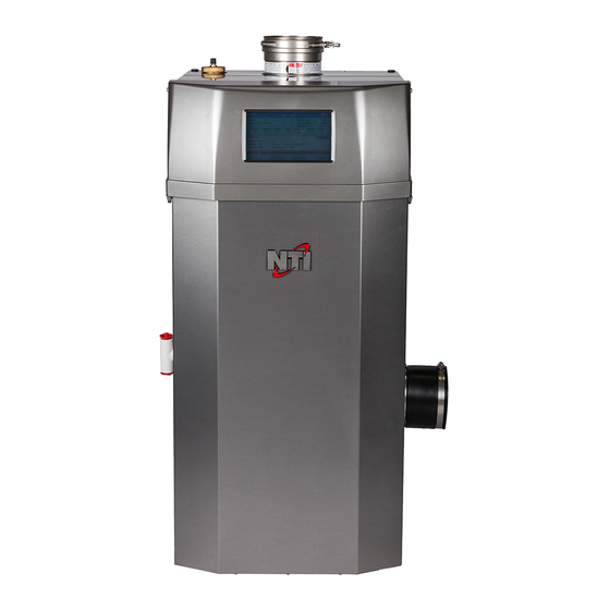
Trinity Lx - WH
Model Numbers: Lx200WH - Lx800WH
Version Date: 2018-07-11
INSTALLATION AND OPERATION INSTRUCTIONS FOR
TRINITY Lx WATER HEATER
TABLE OF CONTENTS
1.0
INTRODUCTION ................................................................................................................ 3
2.0
SPECIFICATIONS .............................................................................................................. 6
3.0
WATER HEATER LOCATION .......................................................................................... 7
4.0
GENERAL VENTING ....................................................................................................... 12
5.0
VENT AND AIR-INTAKE TERMINATION CLEARANCES ........................................ 27
6.0
CONDENSATE DRAIN .................................................................................................... 30
7.0
INSTALLING GAS PIPING .............................................................................................. 31
8.0
LIGHTING THE WATER HEATER ................................................................................ 33
9.0
GAS VALVE AND BURNER SET-UP ............................................................................ 35
10.0 WATER HEATER PIPING ............................................................................................... 42
11.0 LEAD LAG INSTRUCTIONS ........................................................................................... 51
12.0 FIELD WIRING ................................................................................................................. 54
13.0 WIRING SCHEMATICS ................................................................................................... 60
14.0 INSTALLATION CHECKLIST ........................................................................................ 64
15.0 ANNUAL MAINTENANCE AND INSPECTION ........................................................... 65
16.0 PARTS LIST ...................................................................................................................... 67
17.0 TROUBLESHOOTING ..................................................................................................... 79
HAZARD SYMBOLS AND DEFINITIONS
Danger Sign: Indicates a hazardous situation which, if not avoided, will
result in serious injury or death.
Warning Sign: Indicates a hazardous situation which, if not avoided,
could result in serious injury or death.
Caution Sign plus Safety Alert Symbol: Indicates a hazardous situation
which, if not avoided, could result in minor or moderate injury.
Caution Sign without Safety Alert Symbol: Indicates a hazardous
situation which, if not avoided, could result in property damage.
Notice Sign: Indicates a hazardous situation which, if not avoided,
could result in property damage.
This Water Heater must be installed by a licensed and trained Heating
Technician or the Warranty is Void. Failure to properly install this
unit may result in property damage, serious injury to occupants, or
possibly death.
H
Visit us
online
NTI # 85236
Advertisement
Table of Contents

Summarization of Contents
1.0 INTRODUCTION
General Installation Requirements
Standards and codes for installation.
User Responsibilities
Owner's responsibilities for operation and maintenance.
Installer Responsibilities
Installer's responsibilities for safe installation and user guidance.
ATTENTION: LIQUEFIED PETROLEUM (LP) PROPANE
Water heater Vent / Air-Inlet Piping
Requirements for venting and air intake for LP gas operation.
IN THE STATE OF MASSACHUSETTS ONLY
INSTALLATION OF CARBON MONOXIDE DETECTORS
Requirements for CO detector installation in Massachusetts.
EXEMPTIONS
Exemptions from Massachusetts installation rules.
MANUFACTURER REQUIREMENTS – GAS EQUIPMENT VENTING SYSTEM PROVIDED
Manufacturer's obligations for supplied venting systems.
MANUFACTURER REQUIREMENTS – GAS EQUIPMENT VENTING SYSTEM NOT PROVIDED
Manufacturer's obligations for non-provided venting systems.
2.0 SPECIFICATIONS
High Altitude Operation
Guidelines for operating the water heater at elevated altitudes.
3.0 WATER HEATER LOCATION
Floor Mounting
Instructions for mounting the water heater on the floor.
Water heater Area Ventilation Air Openings
Ventilation requirements for the appliance's installation area.
Indoor Combustion Air
Using indoor air for combustion and ventilation.
Closet Installations
Specific installation requirements for closets.
Alcove Installations
Specific installation requirements for alcoves.
Residential Garage Installations
Requirements for installing in garages.
Wall Mounting Installations (Optional)
Optional method for mounting the water heater on a wall.
4.0 GENERAL VENTING
Removing an Existing Water heater from Common Venting System
Procedures for removing a unit from a shared vent system.
Steps to Removing an Existing Water Heater
Detailed steps for removing a water heater from a vent system.
8.0 LIGHTING THE WATER HEATER
FOR YOUR SAFETY, READ BEFORE OPERATING
Safety warnings specific to the lighting process.
OPERATING INSTRUCTIONS
Step-by-step guide for lighting the water heater.
TO TURN OFF GAS TO THE WATER HEATER
Procedure for safely turning off the gas supply.
9.0 GAS VALVE AND BURNER SET-UP
Gas Line Pressure
Procedures for checking and adjusting gas line pressure.
10.0 WATER HEATER PIPING
Water Heater System Preparation
Steps to prepare the system before connecting piping.
Water Chemistry
Recommended water parameters and chemistry.
Potable Water Systems
Suitability and requirements for potable water systems.
Definitions of Potable Water Systems
Definitions of different potable water system types.
11.0 LEAD LAG INSTRUCTIONS
Multiple Water Heater Applications
Capabilities for staging multiple water heaters in a cascade.
Lead Lag Instructions
Setup and configuration for lead-lag water heater systems.
Plumbing
Plumbing configuration for cascade systems.
Water Heater Pump
Control and sizing of water heater pumps in a cascade.
Communication Wiring
Wiring requirements for inter-heater communication.
System Sensor
Configuration of system sensors for cascade operation.
Modbus Address
Assigning Modbus addresses for cascade communication.
Master Enable
Enabling the master unit in a cascade system.
Tank Thermostat
Connecting the tank thermostat for cascade control.
DHW Setpoint
Setting the DHW setpoint on the master unit.
DHW switch (Lead Lag)
Configuring the DHW switch for lead-lag operation.
DHW enable (Local)
Disabling local DHW control for cascade setup.
12.0 FIELD WIRING
Line Voltage Connections
Connecting the 120VAC power supply to the unit.
Fuses (120VAC)
Location and function of fuses protecting the 120VAC circuits.
Pump Relays (Lx500WH-Lx800WH)
Using pump relays in specific models for high capacity pumps.
Wire Protection
Ensuring wiring is protected from chafing and damage.
Power Supply
Requirements for the 120VAC power supply.
Labeling
Importance of labeling wires before disconnection during servicing.
Continuity
Performing continuity checks on wiring.
Max Load
Load limits for circulator outputs.
14.0 INSTALLATION CHECKLIST
Installation
Checklist items to confirm during installation.
Start-up
Steps to follow for starting up the water heater.
Operational Checklist
Checks to perform for ensuring proper operation.
Before Leaving
Final checks before concluding the installation.
Instructions to Installing Contractor
Guidance for contractors on customer handover.
15.0 ANNUAL MAINTENANCE AND INSPECTION
Annual Inspection Checklist
Items to inspect annually for maintenance.
Combustion Chamber Cleaning Procedure
Step-by-step guide for cleaning the combustion chamber.
Cleaning Checklist
Checklist items for the combustion chamber cleaning process.
16.0 PARTS LIST
Commercial Models (Lx500WH-Lx800WH)
Parts specific to commercial models Lx500WH-Lx800WH.
17.0 TROUBLESHOOTING
Servicing the Water heater
General precautions to observe when servicing the unit.
Check 120VAC and 24VAC at the Water heater
Verifying the presence of 120VAC and 24VAC power supplies.


Need help?
Do you have a question about the Lx800WH and is the answer not in the manual?
Questions and answers