Table of Contents
Advertisement
GF 200 Installation Manual
Combination gas-fired, condensing
instantaneous hot water heater and space heating fan coil
* Lead Free
Keep this manual near this appliance for future reference
whenever maintenance or service is required.
* The wetted surface of this product contacted by consumable water contains
less than one quarter of one percent (0.25%) of lead by weight.
WARNING
This appliance (GF 200) is a combination gas-fired, condensing, instantaneous hot water heater
and space heating fan coil. The water heater is a CSA-certified product in its own right and, as
such, must be installed according to its installation and operation manuals (supplied).
This manual provides installation instructions for the GF 200, but defers to the water heater's
manual(s) where appropriate. Throughout, in any conflict between instructions from this manual
and those from the water heater's, the latter are assumed to be correct. When reading the water
heater's manual, only sections pertaining to the NPE-240A model may apply.
If the information in these instructions is not followed exactly, a fire or explosion may result,
causing property damage, personal injury or death.
Do not store or use gasoline or other flammable vapors and liquids in the vicinity of this or any
other appliance.
What to do if you smell gas
Do not try to light any appliance.
●
Do not touch any electrical switch; do not use any phone in your building.
●
Immediately call your gas supplier from a neighbor's phone. Follow the gas supplier's instructions.
●
If you cannot reach your gas supplier, call the fire department.
●
Installation and service must be performed by a qualified installer, service agency or the gas supplier.
The installation must conform with local codes or, in the absence of local codes, the National Fuel
Gas Code, ANSIZ223.1/NFPA 54 and/or CSA B149.1, Natural Gas and Propane Installation Code.
When applicable, the installation must conform with the Manufactured Home Construction and
Safety Standard, Title 24 CFR, Part 3280 and/or CAN/CSA Z240 MH Series, Mobile Homes.
Advertisement
Table of Contents

Related Manuals for NTI GF 200


Summary of Contents for NTI GF 200
- Page 1 The water heater is a CSA-certified product in its own right and, as such, must be installed according to its installation and operation manuals (supplied). This manual provides installation instructions for the GF 200, but defers to the water heater’s manual(s) where appropriate. Throughout, in any conflict between instructions from this manual and those from the water heater’s, the latter are assumed to be correct.
-
Page 2: Table Of Contents
Contents 1. Important Information 1.1 Safety Information 2. About the Appliance Items Included 2.2 Accessories 2.3 Specifications 2.4 Front Panel 2.5 Components 2.6 Dimensions 2.7 Rating Plate 3. Installing the Appliance 3.1 Choosing an Installation Location 3.2 Installation Clearances 3.3 Connecting the Gas Supply 3.4 Connecting the Water Supply 3.5 Connecting the Condensate Drain 3.6 Venting the Appliance... -
Page 3: Important Information
(supplied). This manual provides installation instructions for the GF 200, but defers to the water heater’s manu- DANGER al(s) where appropriate. Throughout, in any conflict between instructions from this manual and those from the water heater’s, the latter are assumed to be... - Page 4 WARNING CAUTION Do not turn on the appliance unless the water and ● gas supplies are fully opened. Doing so may damage the appliance. Do not turn on the water if the cold water supply ● shut-off valve is closed. Doing so may damage the appliance.
-
Page 5: About The Appliance
75,000 Instantaneous 1995 rating plate located under access conformément ; sinon, suivez B149.1, d'installation, VOTRE SÉCURITÉ entreposer utiliser d'essence liquides inflammables à proximité tout autre appareil. codes ANSI Z223.1 naturel échéant. d'autres panel opposite side cabinet. GF 200 Installation Manual... -
Page 6: Specifications
2.3 Specifications The following table lists the specifications for the appliance. Additional specifications about water, gas, electric, and air supplies (venting) appear in the Installation section. Item GF 200 Heat Natural Gas Space Heating: DHW Heating: Capacity 19,900 – 80,000 BTU/H 19,900 –... -
Page 7: Front Panel
2.4 The Front Panel The front panel allows you to adjust the water temperature and view the operating status or error codes. Error A code will appear on the display Hot Water Recirculation Display Recirculation Mode Diagnostics button Up button For installers only Increases the temperature Information button... -
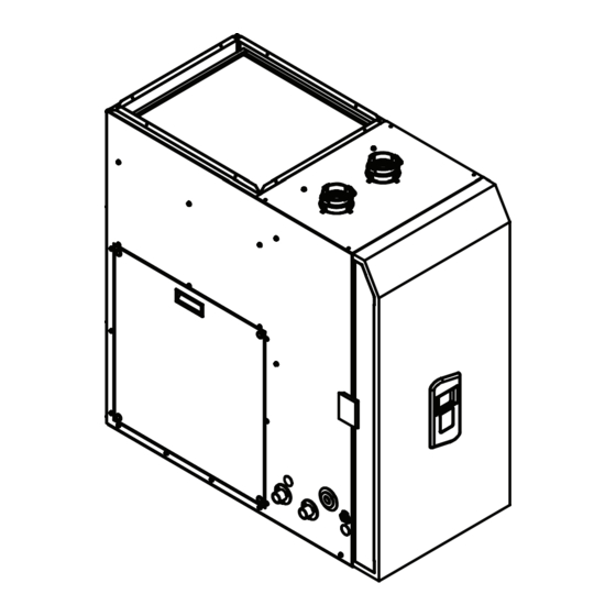
Page 8: Components
PCB Box Gas Valve Water Adjustment Valve Field Wiring Panel Central Heating System Controller Gas Inlet Fitting Condensate Drain DHW Inlet Fitting Water Inlet Filter DHW Supply Fitting Condensate Drain Lid Recirculation Inlet Fitting 3-Way Valve Service Valve GF 200... -
Page 9: Dimensions
2.6 Dimensions The following diagrams show the dimensions of the appliance and the connections. 12.9in 328mm 17.7in 450mm 6.8in 173mm 19.6in 498mm 9.3in 236mm Front 39.7in 1008mm Left Side 19.5in 495mm 10.9in 276mm Gas Conn. Field Wiring Line Voltage Outlet Conn. (3/4" Socket) Condensate Conn. -
Page 10: Rating Plate
##### ##### ##### ##### right side of the cabinet. Certified by Made in Canada GF 200 Certifie par Fabriques au Canada COMBINATION GAS WATER HEATER / CENTRAL AIR HEATING COMBINAISON CHAUFFEE-EAU INSTANTANE / GENERATEUR Rating Plate, *Plaque Signalétique D'AIR CHAUD Direct Vent Automatic Instantaneous Water Heater *Chauffe-eau instantané... -
Page 11: Installing The Appliance
3. Installing the appliance Access to utilities Water – the installation location should be near ● 3.1 Choosing an installation location where the domestic water supply enters the building. This appliance must be installed indoors, in a dry Gas – the installation location should be near location free of dust and debris. -
Page 12: Installation Clearances
3.2 Installation clearances Proximity to fixtures and other appliances Install the appliance near fixtures that deliver or use Install the appliance in an area that allows for service hot water, such as bathroom, kitchen, and laundry and maintenance access to utility connections, room faucets. -
Page 13: Connecting The Gas Supply
3.3 Connecting the Gas Supply To connect the gas supply: 1. Determine the gas type and pressure for the appliance by referring to the rating plate. WARNING 2. Perform a pressure test on the main gas supply line. Before connecting the gas supply, determine ●... - Page 14 Tighten the appliance connection ● Single Regulator System Note valves with care to avoid damage. Refer to the sizing tables on the Gas Regulator ● following pages for limitations. Full size It is recommended that a union be ● Pipe Gas Pipe installed on the gas supply line close to the appliance, to facilitate any future...
- Page 15 3.3.1 Gas Pipe Sizing Tables (Referenced from 2012 National Fuel Gas Code) These tables are for reference only. Please consult the gas pipe manufacturer for actual pipe capacities. Maximum Natural Gas Delivery Capacity in Cubic Feet (ft ) per Hour (0.60 Specific Gravity; 0.5 in WC Pressure Drop). Contact your gas supplier for BTU/ ft3 ratings.
- Page 16 Maximum Liquefied Propane Delivery Capacity in Thousands of BTU/H (0.5 in WC Pressure Drop) Length (including fittings) Pipe 10 ft 20 ft 30 ft 40 ft 50 ft 60 ft 80 ft 100 ft 125 ft 150 ft 175 ft 200 ft 250 ft Size...
-
Page 17: Connecting The Water Supply
3.4 Connecting the Water Supply 3.4.1 Installing the plumbing connections 1. A kit box containing the necessary plumbing When connecting the water supply, follow these connections is shipped inside the cabinet. Remove guidelines: the kit box before installation. Use only pipes, fittings, valves, and other ●... - Page 18 3. Determine which side of the appliance the inlet The following is a typical near-appliance plumbing and outlet water connections will be made on. layout for connections on the same side. A) Left side connections B) Right side connections NOTE: Do not block service door C) Both - One on each side EXPANSION TANK UNION...
- Page 19 RECIRCULATION MODE 3.4.2 Connecting a Pressure Relief Valve This appliance comes factory set for pre-heat recirculation. WARNING 1. The Front Panel DIP switches (set of ten) are Improper installation of the pressure relief valve factory set to: 1—OFF; 2—ON. may result in property damage, personal injury, or death.
-
Page 20: Connecting The Condensate Drain
When installing the valve, follow these guidelines: Before connecting the condensate drain, choose one of the following disposal options: Ensure that the discharge capacity of the pressure ● relief valve is equal to or greater than the maximum pressure rating of the appliance. Ensure that the maximum BTU/H rating on the ●... - Page 21 The appliance is shipped from the factory with a condensate drain pre-installed on the right side. To switch the drain to the left side: 1. Loosen the two (2) metal hose clamps on each end of the tubing inside the cabinet. 2.
-
Page 22: Venting The Appliance
3.6 Venting the Appliance 7. If necessary: to return to the previous menu, press the ‘Reset’ button once. For detailed instrustions on venting the 8. In the Parameter menu, use the Up (+) or Down appliance, see relevant section in the water (-) buttons to proceed to Parameter 10 (‘P.10’), heater installation manual (supplied). -
Page 23: Connecting The Power Supply
3.7 Connecting the Power Supply 3.8 Setting the DIP Switches The appliance has two installer-serviceable DIP WARNING switch locations: on the front panel, and on the interface board, mounted on the frame of the PCB. Improperly connecting the power supply can result in electrical shock and electrocution. - Page 24 10-switch Panel: ● Switch Function Setting Remark 1-OFF; 2-OFF; * Intelligent Preheating: No Recirculation 3-OFF Learns the user's hot water usage patterns and starts Recirculation Mode 1-OFF; 2-ON; preheating prior to an External Recirculation 3-OFF anticipated draw. Preheating starts when ●...
-
Page 25: Ducting The Appliance
3.9 Ducting the appliance b) Rear return: 3.9.1 Supply ducting When routing return air into the back of the unit, an The appliance provides a standard-size flanged opening may be cut within the confines of the supply air outlet for easy installation of a cooling provided holes, taking care not to damage the coil or supply plenum. -
Page 26: Configuring The Appliance
3.10 Configuring the appliance 6. Locate the 4 numbered LEDs (boxed below) that will indicate the air flow programming setting. The appliance is designed to operate with a. Note the 3 unlabeled LEDs (circled below) second-stage (Y2) cooling air flow rates between which will remain lit or flashing throughout 700 and 1450 CFM. - Page 27 The GF 200 protects itself from damage by only ing. allowing the outdoor A/C compressor to run when the circulating fan is within its normal operating envelope (see Appendices).
-
Page 28: Appendices
4. Appendices 4.1 Blower Performance... -
Page 29: Wiring Diagram
4.2 Wiring Diagram (GF 200 + NPE-240A) GF 200 WATER HEATER... -
Page 30: Ladder Diagram
Thermistor 1 Relay 3 Outlet MCU 1 MGV1 MCU 2 Thermistor 2 MGV2 Inlet Relay 1 Thermistor 1 Relay 2 Inlet Relay 4 Thermistor 2 Exhaust Thermistor Communication Interface UART FRONT Communication PANEL Interface Ready Link Ready Link Interface GF 200... -
Page 31: Component Assembly Diagrams
4.4 Component Assembly Diagrams and Parts Lists 4.4.1 Case Assembly... - Page 32 Description Part # Intake Air Duct Assembly 30008662B Intake Air Filter 20007667A Case 20019078C Air Pressure Sensor 30010346A 30011969A Power Switch 30009482A Front Panel 30008333A Case Bracket 20007609A Exhaust Pipe Assembly 30008673A Top Panel Left Side Electrical Cover Logo 81613 Display Bezel 85565 Front Cover...
- Page 33 Description Part # Bottom Door Rail Blower Shelf Spine Hopper, Front Hopper, Left Hopper, Back Hopper, Right Coil Mount Back Top Door Rail Right Top Door Rail Left Side Door Rail Receptacle, 120V 84423 Handle 81622 Door Safety Switch 83208 Right Side Side Door Grommet, Diaphragm 0.5"...
- Page 34 4.4.2 Waterway Assembly 18 17...
- Page 35 Description Part # AHU Extension, 18mm 85246 Pipe Clip, 18mm 85371 O-Ring, 18mm 85369 AHU Inlet, 18mm 85244 Brass Conn. Adapter 85372 Brass Plug Adapter 85523 Pipe, Valve to Valve, 18mm 85524 3-Way Valve, 18mm 85376 3-Way Valve O-Ring 85374 Compression Gasket 82368 Ball Valve, Brass...
-
Page 36: Installation Checklist
4.5 Installation Check list After installing the appliance, review the following checklist. You should be able to answer “Yes” to all of the items in the checklist. If not, review the appropriate sections to complete the installation. If you have additional questions or need assistance with installation, contact Technical Support at 1-800-688-2575. -
Page 37: Troubleshooting
Press Info button to start the test (5-10 seconds on/off cycles for 1 minute) Observe display readout – it should cycle between “On” / “Off” and “_ . _” GPM • If these steps fail to resolve the error, contact NTI Technical Support for further assistance. - Page 38 Plug in connector 'A' while keeping a hand on the 3-way valve motor's white plastic body. • Feel for the motor's steady hum (approx. 3 sec.), pause, and return hum. If these steps fail to resolve the error, contact NTI Technical Support for further assistance.
- Page 39 NOTES...
-
Page 40: Installation Manual
Installation Manual GF 200 Getting Service If your appliance requires service, you have several options for getting service: Contact Technical Support at 1-800-688-2575 or on the website: www.NTIBoilers.com. ● For warranty service, always contact Technical Support first. ● Contact the technician or professional who installed your water heater.
Need help?
Do you have a question about the GF 200 and is the answer not in the manual?
Questions and answers
I have a nti gf 200 furnace throwing a code 438 high flow sensor code, changed it works for 2 weeks a same thing happens again. I tap on water pump an sometimes it works again for couple days. I live in a condo, could I be getting an air lock
Error code 438 on an NTI GF 200 furnace indicates an issue with the circulation pump, specifically an inconsistency between the pump activation signal and the flow sensor reading. Possible causes include:
- Air-lock: During the first central heating call, air may enter the pump, preventing proper operation.
- Faulty Flow Sensor or Pump: The pump may not be generating adequate flow, or the sensor may not be reading it correctly.
To resolve air-lock issues:
- Ensure the air eliminator on top of the pump housing is open.
- Flood the pump chamber to remove trapped air.
This answer is automatically generated