
Related Manuals for Autonics FX6Y-I


Summarization of Contents
(J) Counter / Timer
Product overview
General overview of counter and timer products, including series details.
LA8N Series (Compact LCD Counter)
Introduction to the LA8N series compact LCD counter.
CT Series (Programmable Counter/Timer) Upgrade
Details on the upgraded CT series programmable counter/timer.
FX/FXH/FXL Series (Up/down Counter/Timer)
Overview of FX, FXH, and FXL series up/down counter/timer models.
FS Series (8 pin plug type Counter)
Introduction to the FS series 8-pin plug type counter.
F/L Series (8 digit up/down Counter)
Overview of the F/L series 8-digit up/down counter.
FM/LM Series (Up/down measure Counter)
Introduction to the FM/LM series up/down measure counter.
Application
Examples of how counter and timer products are used.
Technical description
Detailed technical explanations of counter and timer functions.
Product Overview
LA8N Series (LCD type)
Detailed specifications and overview of the LA8N series LCD type.
Product Overview
FX Series
Overview and specifications for the FX series counters/timers.
FXH Series
Overview and specifications for the FXH series counters/timers.
FXL Series
Overview and specifications for the FXL series counters/timers.
FS Series
Overview and specifications for the FS series 8-pin plug counters.
F Series
Overview and specifications for the F series counters.
L Series
Overview and specifications for the L series counters.
FM Series
Overview and specifications for the FM series counters.
LM Series
Overview and specifications for the LM series counters.
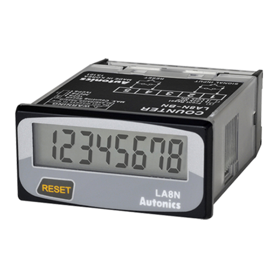
LA8N SERIES
DIN W48×H24mm, Indication only, LCD counter
Specifications and features for the LA8N series DIN W48xH24mm LCD counter.
Features
Key features of the LA8N series counter.
Ordering information
Guide for ordering LA8N series products.
Specifications
Detailed technical specifications for the LA8N series.
Compact LCD Counter
Connections
Wiring diagrams for counter connections.
Dimensions
Physical dimensions and panel cut-out details.
Input connections
Details on input signal connections for various sensor types.
LA8N SERIES
Counter operation mode
Explanation of the counter's operational modes.
Enable / Disable front reset key
Instructions for enabling or disabling the front panel reset.
Selection of counting speed
Guide on selecting different counting speeds.
Case detachment and battery replacement
Procedures for detaching the case and replacing the battery.
CT Series
Programmable Counter/Timer
Introduction to the CT series programmable counter/timer.
Upgraded functions
Details on new and improved functions in the CT series.
Integrated device management program(DAQMaster)
Information on the DAQMaster software for device management.
Ordering information
Guide for ordering CT series products.
CT Series
Specifications
Detailed technical specifications for the CT series.
Communication specification
Details on communication protocols and settings.
CT Series
Connections
Wiring diagrams for various CT series models.
CT Series
Connections
Wiring diagrams for various CT series models, including communication types.
CT Series
Dimensions
Physical dimensions and panel cut-out details for CT series.
Front panel identification
Identification of front panel components and indicators.
CT Series
Input connections
Details on input signal connections for CT series.
Input logic Selection[No-voltage input(NPN)/Voltage input(PNP)]
Selection guide for input logic NPN or PNP.
CT Series
Output connections
Wiring diagrams for output connections.
Factory default
Default parameter settings for the CT series.
Error display
Information on error codes and how to resolve them.
CT Series
Operations and functions
Explanation of operations and key functions.
Change of preset(Counter/Timer)
Procedure for changing preset values.
Function setting check mode
How to check and confirm function settings.
Switching display function in preset indicator
Method for switching display in preset indicators.
Reset
Instructions for resetting the counter/timer.
BATCH Counter(For CT6M-1P/CT6M-2P model only)
Specific functions for BATCH counter in CT6M models.
Change of BATCH setting value
Procedure for changing BATCH setting values.
CT Series
BATCH Counter operation
Explanation of BATCH counter operational modes.
BATCH Counting operation
Details on how BATCH counting operates.
BATCH output
Information on BATCH output behavior.
BATCH reset input
How to use the BATCH reset input.
Application of BATCH Counter function
Examples of BATCH counter applications in counter and timer modes.
CT Series
Flow chart for function setting mode
Visual flowchart for navigating function setting modes.
CT Series
Parameter setting(Counter)
Guide to setting counter parameters.
CT Series
Input operation mode(Counter)
Explanation of different input operation modes for counters.
CT Series
Input operation mode(Counter)
Detailed input modes for counter operation.
Prescale function(Counter)
Explanation and usage of the prescale function.
Start point function(Counter)
Details on how the start point function works.
CT Series
Output operation mode(Counter)
Explanation of various output operation modes for counters.
CT Series
Output operation mode(Counter)
Detailed output modes for counter operation.
Counter operation of the indicator(CT6S-I, CT6Y-I, CT6M-I)
Indicator operation for CT6S-I, CT6Y-I, CT6M-I series.
CT Series
Parameter setting(Timer)
Guide to setting timer parameters.
CT Series
Output operation mode(Timer)
Explanation of various output operation modes for timers.
CT Series
Output operation mode(Timer)
Detailed output modes for timer operation.
CT Series
Output operation mode(Timer)
Further details on timer output operation modes.
CT Series
Timer operation of the indicator(CT6S-I, CT6Y-I, CT6M-I)
Indicator operation for timer functions in CT6S-I, CT6Y-I, CT6M-I.
CT Series
Timer operation of the indicator(CT6S-I, CT6Y-I, CT6M-I)
Detailed indicator operations for timer functions.
CT Series
Timer '0' time setting
How to set timer '0' time for various output modes.
Operation according to output mode (at 0 time setting)
Operational behavior at 0 time setting for different modes.
CT Series
Communication mode
Overview of communication capabilities.
Parameter setting
Settings for communication parameters.
Application of system organization
Diagram showing system organization for communication.
Communication control ordering
Information on ordering communication control systems.
CT Series
Communication command and block
Details on communication command structures.
The format of query and response
Explains the format for query and response in communication.
Read Coil Status (Func 01 H), Read Input Status (Func 02 H)
Commands for reading coil and input status.
Read Holding Registers (Func 03 H), Read Input Registers (Func 04 H)
Commands for reading holding and input registers.
Force Single Coil (Func 05 H)
Command for forcing a single coil.
Preset Single Register (Func 06 H)
Command for preset single register operations.
Preset Multiple Registers (Func 10 H)
Command for preset multiple register operations.
Application
Practical application examples for communication commands.
CT Series
Modbus Mapping Table
Table mapping Modbus addresses to functions and parameters.
Monitoring data
Details on monitoring data points and their status.
Terminal input status
Status of terminal inputs.
Product Information
Information regarding product identification and versions.
Display unit
Information related to the display unit settings.
Preset value setting group
Settings for preset values for counters and timers.
CT Series
Function setting mode (Counter group)
Guide to setting functions for the counter group.
Function setting mode (Timer group)
Guide to setting functions for the timer group.
CT Series
Function setting mode (Communication group)
Guide to setting communication parameters.
Exception processing
Handling of communication exceptions.
Read and write of parameter value using communication
Methods for reading/writing parameters via communication.
Communication control ordering
Information on ordering communication control solutions.
CT Series
Proper usage
Guidelines for correct and safe usage of the CT series.
Input signal line
Recommendations for input signal wiring.
When selecting input logic
Instructions for selecting input logic correctly.
Contact count input(When it is used as Counter)
Considerations for contact input when used as a counter.
When test dielectric voltage and insulation resistance of the control panel with this unit installed
Procedure for testing dielectric and insulation resistance.
Do not use below places.
List of environments where the unit should not be used.
Installation environment
Recommended installation conditions and environment.
Up/Down Counter/Timer
DIN W72×H36mm of counter/timer with indication only
Overview of the DIN W72xH36mm indication-only counter/timer.
Features
Key features of the Up/Down Counter/Timer.
Ordering information
Guide for ordering Up/Down Counter/Timer products.
Specifications
Detailed technical specifications for the Up/Down Counter/Timer.
FXY Series
Connections
Wiring diagrams for the FXY series.
Input connections
Details on input signal connections for FXY series.
Up/Down Counter/Timer
Counting method
Explanation of counting methods for NPN and PNP sensors.
Dimensions
Physical dimensions of the Up/Down Counter/Timer.
Panel cut-out
Panel cut-out dimensions for installation.
Counting operation of indication type(Counter)
Operational examples for indication type counters.
Counting operation of indication type(Timer)
Operational examples for indication type timers.
FXY Series
Description of inner DIP switches
Explanation of the functions of inner DIP switches.
Up/Down mode
DIP switch settings for Up/Down modes.
Counter/Timer
DIP switch settings for Counter/Timer function selection.
Reset function of front panel(ON/OFF)
DIP switch settings for front panel reset function.
Max. counting speed
DIP switch settings for maximum counting speed.
Memory protection (ON/OFF)
DIP switch settings for memory protection.
Time setting mode(Timer)
DIP switch settings for timer time modes.
Up/Down Counter/Timer
Input mode(Counter)
Explanation of input modes for counter operation.
FXY Series
Proper usage
Guidelines for proper usage of the FXY series.
Reset function
Details on the reset function and its signal width.
Using switching pin of Reset / +12V
How to use the switching pin for Reset and +12V.
INHIBIT [For timer]
Explanation of the INHIBIT function for timers.
Sensor power
Information about sensor power supply.
Min.signal width of CP1, CP2 input
Minimum signal width requirements for CP1 and CP2 inputs.
Max. counting speed
Information on maximum counting speed.
Error display
Details regarding error displays and their meanings.
Power
Explanation of power supply behavior.
Case & DIP switch detachment
Instructions for detaching the case and DIP switches.
FXS Series
Up/Down Counter/Timer
Introduction to the FXS series Up/Down Counter/Timer.
DIN W48×H48mm, Preset counter/timer
Specifications for the DIN W48xH48mm preset counter/timer.
Features
Key features of the FXS series counter/timer.
Ordering information
Guide for ordering FXS series products.
Specifications
Detailed technical specifications for the FXS series.
FXS Series
Connections
Wiring diagrams for FXS series models.
Dimensions
Physical dimensions and panel cut-out for FXS series.
Input connections
Details on input signal connections for FXS series.
Up/Down Counter/Timer
Input logic selection
Guide for selecting input logic (NPN/PNP) for FX/FXL series.
Input & output connections
Wiring diagrams for input/output connections.
How to count by external power supply
Instructions for counting using external power supply.
Using 2 counters with one sensor
Method for connecting two counters with a single sensor.
FXS Series
Description of inner DIP switches
Explanation of inner DIP switches for FXS series.
Setting function of Decimal point
Guide to setting the decimal point.
Up/Down Counter/Timer
Input mode(Counter)
Explanation of various input modes for counters.
FXS Series
Counting operation of indication type(Counter)
Operational examples for indication type counters.
Time operation of indication type(Timer)
Operational examples for indication type timers.
Time setting mode(Timer)
Guide to setting timer time modes via DIP switches.
Up/Down Counter/Timer
Output operation mode(by internal DIP switch)
Explanation of output modes controlled by DIP switches.
FXS Series
Proper usage
Guidelines for proper usage of the FXS series.
Reset function
Details on the reset function and its requirements.
INHIBIT (For timer)
Explanation of the INHIBIT function for timers.
Min.signal width of CP1, CP2 input
Minimum signal width for CP1, CP2 inputs.
Max. counting speed
Information on maximum counting speed.
Error display
Details regarding error displays and their meanings.
Power
Explanation of power supply behavior.
Case & DIP switch detachment
Instructions for detaching the case and DIP switches.
FX/FXH/FXL Series
Up/Down Counter/Timer
Introduction to the FX/FXH/FXL series Up/Down Counter/Timer.
DIN W72×H72, W48×H96, W144×H72mm counter/timer
Specifications for DIN W72xH72, W48xH96, W144xH72mm models.
Features
Key features of the FX/FXH/FXL series.
Ordering information
Guide for ordering FX/FXH/FXL series products.
Specifications
Detailed technical specifications for the series.
FX/FXH/FXL Series
Specifications
Continuation of detailed specifications.
Connections
Wiring diagrams for FX/FXH/FXL series models.
Up/Down Counter/Timer
Dimensions
Physical dimensions and panel cut-out details for FX/FXH/FXL series.
Input connections
Details on input signal connections for FX/FXH/FXL series.
FX/FXH/FXL Series
Input logic selection
Guide for selecting input logic for FX/FXH/FXL series.
Input & output connections
Wiring diagrams for input/output connections.
How to count by external power supply
Instructions for counting using external power supply.
Using 2 counters with one sensor
Method for connecting two counters with a single sensor.
FX/FXH/FXL Series
Description of inner DIP switches
Explanation of inner DIP switches for FX/FXH/FXL series.
Max. counting speed
DIP switch settings for maximum counting speed.
Counter/Timer
DIP switch settings for Counter/Timer function selection.
Up/Down mode
DIP switch settings for Up/Down modes.
Memory protection
DIP switch settings for memory protection.
1st output one-shot (ON/OFF)
DIP switch settings for 1st output one-shot mode.
Up/Down Counter/Timer
Input mode(Counter)
Explanation of input modes for counter operation.
Up/Down Counter/Timer
Time setting mode(Timer)
Guide to setting timer time modes via DIP switches.
Counting operation of indication type(Counter)
Operational examples for indication type counters.
Time operation of indication type(Timer)
Operational examples for indication type timers.
Setting function of Decimal point
Guide to setting the decimal point.
FX/FXH/FXL Series
Output operation mode
Explanation of output modes based on SW1 settings.
Up/Down Counter/Timer
Proper usage
Guidelines for proper usage of the Up/Down Counter/Timer.
Reset function
Details on the reset function and its requirements.
INHIBIT (For timer)
Explanation of the INHIBIT function for timers.
Min.signal width of CP1, CP2 input
Minimum signal width for CP1, CP2 inputs.
Max. counting speed
Information on maximum counting speed.
Error display
Details regarding error displays and their meanings.
Power
Explanation of power supply behavior.
Case & DIP switch detachment
Instructions for detaching the case and DIP switches.
FS Series
DIN W48×H48mm 8 Pin plug counter
Overview of the FS series DIN W48xH48mm 8-pin counter.
Features
Key features of the FS series counter.
Ordering information
Guide for ordering FS series products.
Specifications
Detailed technical specifications for the FS series.
8 Pin Plug type Counter
Connections
Wiring diagrams for 8-pin plug type counter models.
Dimensions
Physical dimensions and panel cut-out for 8-pin plug counters.
Input connections
Details on input signal connections for 8-pin plug counters.
FS Series
Input & output connections
Wiring diagrams for input and output connections.
Description of inner DIP switches
Explanation of inner DIP switches for FS series.
Max. counting speed
DIP switch settings for maximum counting speed.
Up/Down mode
DIP switch settings for Up/Down modes.
Memory protection
DIP switch settings for memory protection.
Setting function of Decimal point
Guide to setting the decimal point.
8 Pin Plug type Counter
Counting operation of indication mode(Indication model)
Operational examples for indication mode counters.
Output operation mode
Explanation of output modes based on SW1 settings.
FS Series
Proper usage
Guidelines for proper usage of the FS series.
Reset function
Details on the reset function and its requirements.
Min. signal width
Minimum signal width for CP1, CP2 inputs.
Max. counting speed
Information on maximum counting speed.
Error display
Details regarding error displays and their meanings.
Detach the case from body
Instructions for detaching the case.
Power
Explanation of power supply behavior.
F/L Series
8 Digit Up/Down/Up • Down Counter
Introduction to the F/L series 8-digit up/down counters.
Features
Key features of the F/L series counter.
Ordering information
Guide for ordering F/L series products.
Specifications
Detailed technical specifications for the F/L series.
F/L Series
Dimensions
Physical dimensions and panel cut-out for F/L series.
Connections
Wiring diagrams for F/L series models.
8 Digit Up/Down/Up • Down Counter
Input logic selection
Guide for selecting input logic for F/L series.
Input connections
Details on input signal connections for F/L series.
Input & output connections
Wiring diagrams for input/output connections.
F/L Series
Description of inner DIP switches
Explanation of inner DIP switches for F/L series.
Counting operation of indication type
Operational examples for indication type counters/timers.
Setting function of Decimal point
Guide to setting the decimal point.
8 Digit Up/Down/Up • Down Counter
Input mode(Counter)
Explanation of input modes for counter operation.
F/L Series
Output operation mode
Explanation of output modes based on SW1 settings.
FM/LM Series
DIN W72×H72, W144×H72mm of Up / Down / Up • Down measure counter
Overview of FM/LM series measure counters.
Features
Key features of the FM/LM series measure counters.
Specifications
Detailed technical specifications for the FM/LM series.
FM/LM Series
Specifications
Continuation of FM/LM series specifications.
Up/Down/Up Down Measure Counter
Specifications
Detailed specifications for Up/Down Measure Counters.
Connections
Wiring diagrams for Up/Down Measure Counter models.
FM/LM Series
Dimensions
Physical dimensions and panel cut-out for FM/LM series.
Input connections
Details on input signal connections for FM/LM series.
Up/Down/Up Down Measure Counter
Description of inner DIP switches
Explanation of inner DIP switches for FM/LM series.
Input & output connections
Wiring diagrams for input/output connections.
How to count by external power supply
Instructions for counting using external power supply.
Using 2 counters with one sensor
Method for connecting two counters with a single sensor.
FM/LM Series
Selection by DIP switches
Explanation of DIP switch functions for FM/LM series.
Max. counting speed
DIP switch settings for maximum counting speed.
Up/Down mode selection
DIP switch settings for Up/Down modes.
1st output one-shot (ON/OFF)
DIP switch settings for 1st output one-shot mode.
Reset switch of front panel
DIP switch settings for front panel reset.
Measure function
DIP switch settings for measure function (Multi/Divide).
Counting operation of indication type
Operational examples for indication type counters/timers.
Setting function of Decimal point
Guide to setting the decimal point.
Up/Down/Up Down Measure Counter
Input operation mode
Explanation of input modes for counters.
Up/Down/Up Down Measure Counter
Output operation mode
Explanation of output modes based on SW1 settings.
FM/LM Series
Output operation mode
Explanation of output modes based on SW1 settings.
FM/LM Series
Proper usage
Guidelines for proper usage of the FM/LM series.
Reset function
Details on the reset function and its requirements.
Min. signal width
Minimum signal width for CP1, CP2 inputs.
Max. counting speed
Information on maximum counting speed.
Error display
Details regarding error displays and their meanings.
Detach the case from body
Instructions for detaching the case.
Power
Explanation of power supply behavior.
Input signal line
Recommendations for input signal wiring.
Test circuit dielectric, impulse voltage and measure insulated resistor by installing in control panel
Procedure for testing dielectric and insulation resistance.
Do not use below places.
List of environments where the unit should not be used.
Installation environment
Recommended installation conditions and environment.
Applications
Quantity control
Examples of quantity control applications.
Length measurement
Examples of length measurement applications.
Applications
Position control
Examples of position control applications.
Length measurement
Examples of length measurement applications.
Quantity control
Examples of quantity control applications.
Technical Description
Overview and principle
General overview and operating principles of electronic counters.
Electronic counter
Basic structure and components of an electronic counter.
Preset counter
Explanation of a preset counter's operation.
Indicator counter
Explanation of an indicator counter's function.
Input mode
Overview of available input operation modes.
Technical Description
Down mode
Explanation of Down mode input operations.
About Counting
Definitions and concepts related to counting.
Maximum counting speed
Definition and calculation of maximum counting speed.
Zero blanking
Explanation of the zero blanking function.
Memory protection
Explanation of the memory protection function.
Reset
Explanation of different reset methods.
Technical Description
Automatic reset
How the counter resets automatically.
Reset signal width
Minimum signal width requirements for reset.
Input
Explanation of input signal types.
Contact input signal
Details on contact input signals.
Output
Explanation of output signal types.
Solid state output
Explanation of solid-state output signals.
NPN open collector output
Details on NPN open collector output.
Technical Description
Allowable inflow current
Maximum permissible inflow current for transistors.
Allowable voltage
Maximum allowable voltage for transistor operation.
Relay contact output
Explanation of relay contact output signals.
Contact organization
Explanation of different contact types (SPST, SPDT, DPST, DPDT).
Proper usage
Guidelines for proper usage and countermeasures.
Signal input line
Recommendations for input signal wiring practices.
Technical Description
Power supply
Guidelines for power supply wiring and stability.
Noise
Methods for reducing noise interference.
Environment
Avoidance of unsuitable environmental conditions.
Need help?
Do you have a question about the FX6Y-I and is the answer not in the manual?
Questions and answers