Table of Contents
Advertisement
Quick Links
DRW161279AD
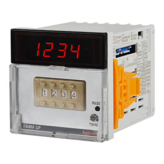
Digital Counters / Timers
FXM / FXH Series
PRODUCT MANUAL
For your safety, read and follow the considerations written in the instruction
manual, other manuals and Autonics website.
The specifications, dimensions, etc. are subject to change without notice for product
improvement. Some models may be discontinued without notice.
Features
• Counting speeds: 1 cps / 30 cps / 2 kcps / 5 kcps
• Switch between counter and timer operation using DIP switch
• No-voltage input (NPN) using DIP switch
• Operation modes: count-up, count-down, count-up / down
• Set decimal point, hr / min / sec display with RESET key
[Counter]
• 20 input modes, 18 output modes
[Timer]
• Various output modes (16 output modes)
• Various time setting ranges:
- 8-digit models: 0.01 sec to 99999 hr 59.9 min
- 6-digit models: 0.1 sec to 99999.9 hr
- 4-digit models: 0.01 sec to 9999 hr
• Output model types: single preset, dual preset, indicator only
• Power supply: 100 - 240 VACᜠ 50 / 60 Hz
ᜢ ᜧ ᜫ
Safety Considerations
• Observe all 'Safety Considerations' for safe and proper operation to avoid hazards.
• symbol indicates caution due to special circumstances in which hazards may occur.
Warning
Failure to follow instructions may result in serious injury or death.
01. Fail-safe device must be installed when using the unit with machinery that
may cause serious injury or substantial economic loss. (e.g. nuclear power
control, medical equipment, ships, vehicles, railways, aircraft, combustion
apparatus, safety equipment, crime / disaster prevention devices, etc.)
Failure to follow this instruction may result in personal injury, economic loss or fire.
02. Do not use the unit in the place where flammable / explosive / corrosive gas,
humidity, direct sunlight, radiant heat, vibration, impact, or salinity may be
present.
Failure to follow this instruction may result in explosion or fire.
03. Install on a device panel to use.
Failure to follow this instruction may result in fire or electric shock.
04. Do not connect, repair, or inspect the unit while connected to a power
source.
Failure to follow this instruction may result in fire or electric shock.
05. Check 'Connections' before wiring.
Failure to follow this instruction may result in fire.
06. Do not disassemble or modify the unit.
Failure to follow this instruction may result in fire or electric shock.
Caution
Failure to follow instructions may result in injury or product damage.
01. When connecting the power / sensor input and relay output, use AWG 20
(0.50 mm
) cable or over, and tighten the terminal screw with a tightening
2
torque of 0.74 to 0.90 N m.
Failure to follow this instruction may result in fire or malfunction due to contact
failure.
02. Use the unit within the rated specifications.
Failure to follow this instruction may result in fire or product damage.
03. Use a dry cloth to clean the unit, and do not use water or organic solvent.
Failure to follow this instruction may result in fire or electric shock.
04. Keep the product away from metal chip, dust, and wire residue which flow
into the unit.
Failure to follow this instruction may result in fire or product damage.
Cautions during Use
• Follow instructions in 'Cautions during Use' .
Otherwise, it may cause unexpected accidents.
• Use the product, 0.1 sec after supplying power.
• When supplying or turning off the power, use a switch or etc. to avoid chattering.
• Install a power switch or circuit breaker in the easily accessible place for supplying or
disconnecting the power.
• When the counter is operating, in case of contact input, set count speed to low speed
mode (1 cps or 30 cps) to operate. If set to high speed mode (2 k, 5 kcps) counting
error occurs due to chattering.
• Keep away from high voltage lines or power lines to prevent inductive noise. In case
installing power line and input signal line closely, use line filter or varistor at power line
and shielded wire at input signal line.
Do not use near the equipment which generates strong magnetic force or high
frequency noise.
• This unit may be used in the following environments.
- Indoors (in the environment condition rated in 'Specifications')
- Altitude max. 2,000 m
- Pollution degree 2
- Installation category II
Advertisement
Table of Contents

Related Manuals for Autonics FXM Series


Summary of Contents for Autonics FXM Series
- Page 1 For your safety, read and follow the considerations written in the instruction Do not use near the equipment which generates strong magnetic force or high manual, other manuals and Autonics website. frequency noise. The specifications, dimensions, etc. are subject to change without notice for product •...
- Page 2 Instantaneous SPDT (1c) × 2 Dimensions Capacity 250 VACᜠ 3 A, 30 VDCᜡ 3 A resistive load Solid-state control NPN open collector • Unit: mm, For the detailed drawings, follow the Autonics website. output ■ FXM ■ FXH Type (1-stage) × 1 Type (2-stage) ×...
- Page 3 -|Transparent Guide|- Detach the Case or DIP Switch Cover Input Connections ■ FXM • Push and pull the groove of DIP switch cover with a flat • Input: CP1, CP2 (INHIBIT), RESET head (-) driver to the front, detaching the cover from the •...
- Page 4 -|Transparent Guide|- Input / Output Connections Counter Operation ■ When operation load by ■ When operating load by ■ Input operation mode sensor power external power Counting chart Mode Voltage input (PNP) No-voltage input (NPN) Constant - voltage circuit Sensor Up / Down - A : command Load1...
- Page 5 OUT1 / 2 maintains ON when counting OUT1 / 2 maintains ON when counting display value ≥ 1 / 2-stage setting value. display value ≤ 1 / 2-stage setting value. 18, Bansong-ro 513Beon-gil, Haeundae-gu, Busan, Republic of Korea, 48002 www.autonics.com | +82-51-519-3232 | sales@autonics.com...
Need help?
Do you have a question about the FXM Series and is the answer not in the manual?
Questions and answers