
Related Manuals for APAR AR662


Summary of Contents for APAR AR662
- Page 1 USER MANUAL AR682 AR642 AR662 AR692 AR602 AR652 AR632 PROGRAMMABLE MICROPROCESSOR CONTROLLERS Version 1.5.4 2014.04.29...
-
Page 2: Table Of Contents
Thank you for choosing our product. This manual will help you use your controller correctly, safely and to its full potential. Read this manual carefully before installing and putting your controller to use. In case of additional questions, please contact the technical advisor. CONTENTS 1. -
Page 3: Safety Rules
1. SAFETY RULES read this manual carefully before starting to use the device; to prevent the hazard of electric shock or equipment damage the mechanical and electrical installation should be performed by qualified personnel; before powering the device make sure all leads have been connected correctly; disconnect the power supply before making any modifications of the leads configurations;... -
Page 4: Kit
methods of parameters configuration: - from the keypad on the controller front panel; - via RS485 or AR955 programming device and ARSOFT-WZ1 freeware (Windows 2000/XP/Vista/7) software and AR955 programming device which allows viewing the measured value and a quick configuration of single or ready-to-use parameter sets previously saved in the computer to be reused, for example in other controllers of the same type (configuration duplication);... - Page 5 - output basic error < 0.1 % of output range - top red, height: 7-segment LED display 14 mm (AR652, AR632), 20mm (AR682), 9mm (AR642, (2 lines with 4 digits each, brightness AR602), 10mm (AR662), 25mm (AR692) control) - bottom...
-
Page 6: Dimensions And Installation Data
Leads cross sections (for 2.5mm (power and binary outputs), separable connections) 1.5mm (remaining) b) AR682 board-type, Incabox XT L57 Enclosure type self-extinguishing polycarbonate NORYL Material 94V-0 Enclosure dimensions 96 x 96 x 79mm (W x H x D) -
Page 7: Description Of Terminal Strips And Electrical Connections
P2 or SSR2 relay output, for AR602 P1 or SSR1 output 19-20 (except AR602) P3 or SSR3 relay output a.1) AR642, AR652, AR682 – terminals description Table 7 a.2) AR602 - terminals description Table 7 a.3) AR692, AR632 – terminals description Table 7 (in AR632 PRG socket is accessible on the display board) -
Page 8: Important Tips - Using The Suppression Systems
− now you have access to terminals to connect the signal, power supply, and relay outputs leads; − insert the leads to the controller through cable glands; − after connecting, reassemble the controller in reverse order; − to get the IP65 rating, precisely tighten the glands’ nuts and the enclosure cover; −... -
Page 9: Description Of Buttons And Signal Led Indicators
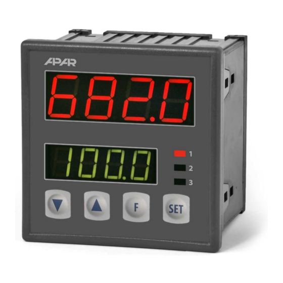
9. DESCRIPTION OF BUTTONS AND SIGNAL LED INDICATORS Description the front 7-segment LED display elevation for example AR652 programming buttons LED indicators a) functions of buttons in the measurement display mode Button Description [and designation in the manual] [UP] or [DOWN]: change set value for input 1 (parameter 9: or 26: when output 1 is in manual mode (see sections 10 and 12.8) -
Page 10: Setting The Configuration Parameters
Table 9.1. Available functions of button [F] and input BIN Source Description (depending on the value of parameter 34: Func ) Message Func = nonE button [F] and input BIN inactive (factory setting) Func = Set3 discrete change of set value for P1/SSR1 output Set1 / Set3 (day = parameter 9: Set1 /night = 16: Set3 , Table 10) Func = bLoc keypad locked (except button [F]) - Page 11 NOTE: - before disconnecting the controller from the computer press the Disconnect Device button (ARSOFT-WZ1) - if the program does not respond: in Program Options check the port configuration and the MODBUS device address make sure that the serial port drivers in the computer have been correctly installed for the RS485 converter or the AR955 programming device disconnect the RS485 converter or the AR955 programming device for a few seconds and then reconnect...
- Page 12 3: Lo1 low limit 1 or /99.9 ÷ 1800 low settings limit for the set value 9: Set1 /99.9 °C bottom of indications /999 ÷ 9999 indications for 0/4mA, 0V, 0Ω – beginning of input scale (2) range (2) /99.9 ÷ 1800 high settings limit for the set value 9: Set1 4: Hi1 high limit 1 or top of 850.0 °C...
- Page 13 PID algorithm integration time, 23: ti PID integration time 0 ÷ 3600 sek. 0 switches off the PID algorithm’s integration module constant PID algorithm differentiation time, 24: td PID differentiation 0 ÷ 999 sek. 0 switches off the PID algorithm’s differentiation module time constant 25: tc pulsing period 3 ÷...
-
Page 14: Quick Access Menu
11. QUICK ACCESS MENU The measurement mode (measured value display mode) provides an opportunity of an immediate access to some configuration parameters and functions without entering the password. This opportunity is called quick access and is available after pressing the [SET] button. The selection and editing of the parameter is analogous to the description in section 10. -
Page 15: Types Of Output Characteristics
12.2. TYPES OF OUTPUT CHARACTERISTICS Type of operation of each output is programmed using the parameters 8: out1, 12: out2, and 15: out3, section 10, Table 10. a) basic outputs characteristics curves b) additional outputs characteristics curves (only for outputs 2 and 3) NOTE: * H3 is constant and equals 0.2°C (2 units), not subject to configuration... -
Page 16: Analogue Output
12.3. ANALOGUE OUTPUT The output signal standard is determined by parameter 17: AtYP (section 10, Table 10). The analogue output can be used in one of the following modes: measurement retransmission (parameter 18: outA = rEtr), manual (18: outA = hAnd) and as an automatic control output (18: outA = cont). In the measurement retransmission mode, the output signal is proportional to the signal measured in the range set by parameters 19: A-Lo and 20: A-Hi (e.g. -
Page 17: Automatic Selection Of Pid Parameters
12.5. AUTOMATIC SELECTION OF PID PARAMETERS The first step to use the function of PID parameters selection is to choose the type of tuning (parameter 21: tunE, section 10). The tuning will start automatically with start of control (after powering up, and also by pressing the button [F], or by binary input BIN when parameter 34: Func = StSP, section 9.1). -
Page 18: Adjustment Of Pid Parameters
The program can discontinue the autotuning b or c (with the Errt message) if the conditions for correct algorithm operation are not met: initial value is higher than the set value for heating or lower for cooling; maximum autotuning duration (4 hours) has been exceeded; process value changes too quickly or too slowly. -
Page 19: Manual And Remote Control Option
12.8. MANUAL AND REMOTE CONTROL OPTION The manual mode allows to set the output signal over its whole range (0 ÷ 100% ), and consequently the enables the open control loop operation (no automatic relationship between the measured value and the output signal). The manual mode is available independently for each controller output and is programmable by the parameters 8: out1, 12: out2,15: out3 and 18: outA section 10, Table 10. -
Page 20: Rs485 Communication Interface (Acc. To Eia Rs-485)
− display current measuring data from maximum 30 channels simultaneously (only the ARSOFT-WZ2 APAR devices) (paid) − software requires communication with the controller via the RS485 or PRG (AR955) The detailed descriptions of these applications are included in the installation folders. -
Page 21: Modbus-Rtu Serial Transmission Protocol (Slave)
16. MODBUS–RTU SERIAL TRANSMISSION PROTOCOL (SLAVE) Format : 8 bits, 1 stop bit, no parity bit Available function : READ - 3 or 4, WRITE - 6 Table 16.1. Claim frame format for the READ function (frame length – 8 bytes): number of registers to be device function... - Page 22 0x08 (8) -100 ÷ 700 temperature of thermocouples cold ends (resolution 0.1°C ) 0x09 ÷ 0x10 not used or reserved Configuration parameters (section 10) 0x11 (17) 0 ÷ 16 parameter 0: inP type of measuring input (section 10) 0x12 (18) 1 ÷...
-
Page 23: Notes
17. NOTES... - Page 25 Temperature Sensor Modules Click to view products by manufacturer: Apar Other Similar products are found below : HPP809A031 MBT 3560-0000-0050-10-110 MBT 3560-0000-0100-10-110 MBT 3560-0001-0050-10-120 MBT 3560-0001-0100-10-120 TCN4L-22R TCN4M-22R TX4H-14R TX4H-24R TX4H-A4R TX4H-B4R TX4L-14R TX4L-A4R TX4L-B4R TX4M-14R TX4M-24C TX4M-24R TX4M-A4R TX4M-B4R 2924799 2811828 QP99 CP82 CP99 R38-LAOO R38-LARR 72-11304023-0150.0050 72-11304027- 0150.0050 72-23304003-0150.0050.GGP 72-23904001-0300.0040.TM 72-34904001-0300.0040.TM AT403-414-1000 AT403-614-1000 AT-...
Need help?
Do you have a question about the AR662 and is the answer not in the manual?
Questions and answers