Table of Contents

Related Manuals for APAR AR662.B


Summarization of Contents
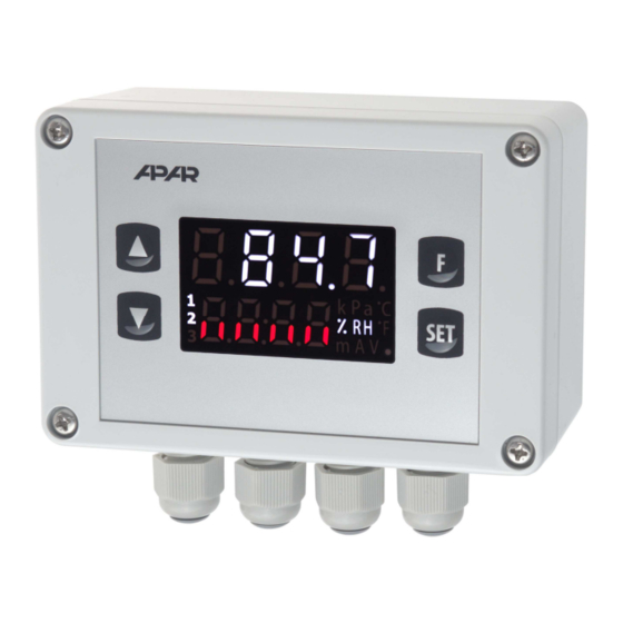
Housing Dimensions and Assembly Data
Model-Specific Housing and Dimensions
Details on physical dimensions and mounting for various controller models (AR602.B, AR642.B, AR652.B, AR682.B, AR662.B, AR632.B).
Description of Clamping Rails and Electrical Connections
Connector Descriptions and Layouts
Detailed diagrams and pin assignments for controller connectors across different models.
Wiring and Connection Types
Guidance on electrical connections, including converter and relay types.
Description of Keys and LED Display Functions
Key Functions Overview
Details on key operations in measurement, configuration, and quick access modes.
LED Display and Input Methods
Functions of LED segments and binary input for device operation and configuration.
Output Operation Configuration
9.1. Change of Setpoints and Quick Access Menu
Procedure for adjusting setpoints and accessing quick menu functions.
9.2. Analog Output (mA/V) Configuration
Settings for analog output types, scaling, and functions.
9.3. PID Control Algorithm
Explanation and configuration of the Proportional-Integral-Derivative control algorithm.
9.4. Automatic PID Parameter Selection
Methods and procedures for automatically tuning PID parameters.
9.5. PID Parameter Correction
Guidelines for manually adjusting PID parameters to optimize performance.
9.6. Programmed Work Characteristics
Setting up multi-stage control programs with time-based segments.
9.7. Mixing Valve Control Configuration
Specific configuration for controlling mixing valves using servo algorithms.
Signaling Messages and Errors
Measurement Error Codes
Descriptions and potential causes for measurement-related errors.
Temporary Errors and Status Messages
Interpreting periodic errors and system status notifications.
Serial Communication, Software, and USB Drivers
11.1. MQTT Protocol Configuration
Setting up the MQTT protocol for IoT data transmission.
11.2. MODBUS-TCP Protocol Details
Information on using the MODBUS-TCP protocol over Ethernet.
11.3. RS485 Communication Interface
Specifications and setup for RS485 serial communication.
11.4. MODBUS-RTU Protocol Details
Information on using the MODBUS-RTU protocol over RS485.
11.5. Device Register Map for MODBUS-RTU/TCP
Register addresses and data mapping for MODBUS communication.
Need help?
Do you have a question about the AR662.B and is the answer not in the manual?
Questions and answers