Table of Contents

Related Manuals for APAR AR653


Summary of Contents for APAR AR653
- Page 1 APAR - SALES OFFICE 05-090 Raszyn, ul. Gałczyńskiego 6, Poland Tel.: +48 22 101-27-31, +48 22 853-49-30 E-mail: automatyka@apar.pl Website: www.apar.pl USER MANUAL AR653 AR663 UNIVERSAL TWO-CHANNEL CONTROLLERS Version 1.1.5 2016.02.24...
-
Page 2: Table Of Contents
Thank you for choosing our product. This manual is intended to facilitate correct operation, safe use, and taking full advantage of the controller's functionalities. Before you start the device, please read and understand this manual. In the event of any additional questions, please contact our technical adviser. CONTENTS 1. -
Page 3: Safety Rules
1. SAFETY RULES before you start to use the device, become familiar with the present instructions in order to avoid electrocution or damage to the device, its mechanical and electrical installation must be performed by qualified workers; before switching on the power supply, make sure that all cables and wires are properly connected; before making any modifications to the wire and cable connections, switch off the voltage supplied to the device;... -
Page 4: Contents Of The Set
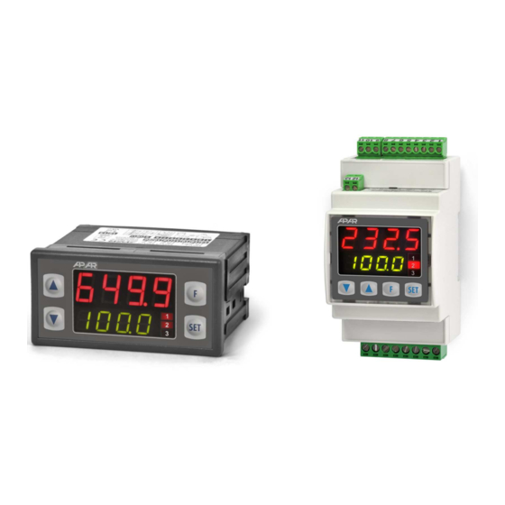
(copying of configuration); AR653 - panel enclosure (IP65 on the front); AR663 - enclosure for the DIN35 rail (IP20); options to be selected (in the ordering method): 24 V AC/DC power supply, SSR control outputs, 0/2-10 V analog output, and RS485 interface;... - Page 5 0 ÷ 50 °C, <90% RH (no condensation) Operating environment air and neutral gases Protection rating AR653 - panel, IP65 from the front, IP20 from the side of the connections AR663 - enclosure for the DIN35 rail, IP20 AR653 ~200 g, AR663 ~160 g...
-
Page 6: Enclosure Dimensions And Installation Data
P2 or SSR2 19-20 transmitter output P3 or SSR3 a) numbering of connections on the back panel and method of connecting sensors and measurement signals a.1) AR653 (clamp terminal description Table 7 a.2) AR663 (clamp terminal description Table 7) -
Page 7: Important Tips - Using The Suppression Systems
9. FUNCTIONS OF BUTTONS AND LED INDICATORS Description of the front 7-segment LED displays side using the example of the AR653 device programming buttons LED diodes a) button functions in the measurement display mode Button... -
Page 8: Function Button
[UP] and [DOWN] (at the same time): input in the parameter configuration menu (after hold time longer than 1 s). If parameter 49: PPro = on (password protection is activated) enter the access code (chapter 10) [F]: activation of a function programmed with parameter 50: Func (after holding for more than 1 second, chapters 9.1 and 10) b) button functions in the parameter configuration menu and the quick access menu (chapters 10 and 11) Button... -
Page 9: Setting Of The Configuration Parameters
10. SETTING OF THE CONFIGURATION PARAMETERS All the controller's configuration parameters are saved in a non-volatile (permanent) internal memory. When the device is switched on for the first time, an error message may be shown in the display due to the lack of a sensor or the fact that the sensor that is connected or not one that is factory-programmed. - Page 10 Table 10. List of configuration parameters Parameter Range of variability of the parameter and description Default DISPLAY OPTIONS – submenu diSP 0: diS1 value for the upper inP1 = measurement from input 1, inP2 = measurement from input 2, inP1 display Subt = difference between measurements (1-2), Addi = sum of measurements (1+2), AvrG = average value of measurements (sum of...
- Page 11 MAIN OUTPUT CONFIGURATION (P1/SSR1) – submenu out1 - chapter 12 (12.2) inP1 = measurement from input 1, inP2 = measurement from input 2, Subt 17: coS1 control signal for = difference between measurements (1-2), Addi = sum of measurements inP1 output 1 (assignment of (1+2), AvrG = average value of measurements (sum of measurements from input)
- Page 12 CONFIGURATION OF THE PID ALGORITHM AND THE MANUAL MODE – submenu PidH oFF = off, Auto = automatic selection (continuous tuning), StEP = run-up 37: tunE type of PID tuning (quick) method, oSct = oscillation (slower) method, chapter 12.5 0.0 ÷ 1800 or 0 ÷ 9999 units (2), 0 - switches off the PID's action, a 38: Pb range of PID 0.0 °C description of the PID algorithm and associated topics can be found in...
-
Page 13: Quick Access Menu
Notes: (1) – for FiL = 1 the response time is equal to 0.5 s, for FiL = 20 it is equal to at least 4 s. Higher degree of filtration means a "smoother" measured value and a longer response time, which is recommended in the case turbulent measurements (e.g. -
Page 14: Analog Output
a) basic operating characteristics of outputs b) additional operating characteristics of outputs (applies only to outputs 2 and 3) 12.3. ANALOG OUTPUT The standard of the output signal is determined by parameter 33: AtYP (chapter 10, Table 10). The analog output can work in one of the following modes: retransmission of measurement (parameter 34: outA = rEtr ), manual mode (34: outA = hAnd ) and as an automatic control output (34: FunA = out1 ). -
Page 15: Pid Regulation
parameters 35: A-Lo and 36: A-Hi (e.g. 0 mA for the measured value 0 °C when A-Lo = 0 °C, 20 mA for 100 °C when A-Hi = 100 °C and, as appropriate, 10 mA for the half of the range, i.e. 50°C ). Manual operation (chapter 12.8) enables smooth change of the output signal in the range of 0-100% with an increment of 1% and the initial value equal to the last value in the automatic mode (measurement retransmission or control mode, applies to the controller firmware release starting from u-13, which is displayed when power is... -
Page 16: Automatic Pid Parameter Selection
12.5. AUTOMATIC PID PARAMETER SELECTION The first step to use the PID parameter selection function is to choose the type of tuning (parameter 37: tunE , chapter 10). The tuning is started automatically when the control starts (after the power supply is switched on, and by pressing the [F] function button, when parameter 50: Func = StSP , chapter 9.1). -
Page 17: Pid Parameter Correction
The algorithms described in items b and c comprise the following steps: - delay of output switch-on (approx. 15 s); - time for switching on the power supply of the operating element (heating/cooling power, fan, etc.); - determination of the object's characteristics; - calculation and saving in the controller's permanent memory parameters 38: Pb , 39: ti , 40: td and 41: tc - switching on the regulation with new PID settings;... -
Page 18: Manual And Remote Control Function
The successive steps of the process are shown on any display by messages shown every few seconds, alternately with the current displayed value: - Pr-1 - stage 1 - reaching the value of threshold 20: SEt1 with set gradient (44: rAr) - ramping - Pr-2 - stage 2 - implementation of the 1st holding time 45: th1 on level SEt1 (with hysteresis 21: H1 ), value of parameter th1 = 0 maintains step Pr-2 permanently - Pr-1 - stage 3 - reaching the value of threshold 25: SEt2 with full power... -
Page 19: Connecting The Controller To A Computer And Available Software
Communication with devices is effected using a protocol compatible with MODBUS-RTU (chapter 16). The following applications are available (on a CD supplied with the AR955/956 programmer or to be downloaded from the Internet at www.apar.pl, Download section, for operating systems Windows Vista/7/8/10):... -
Page 20: Rs485 Communication Interface (Acc. To Eia Rs-485)
15. RS485 COMMUNICATION INTERFACE (acc. to EIA RS-485) It may be useful (or necessary) to connect the controller to a computer in the following situations: The installation specification for the RS485 interface is the following: Maximum cable length - 1 km Maximum number of devices in a RS485 line - 30, in order to increase the number, use RS485/RS485 amplifiers Termination resistors when the MASTER is at the start of the line (see the figure above):... - Page 21 Table 16.3. Response frame format for the READ function (minimum frame length - 7 bytes): number of bytes in the address of function 4 or data field (max. 70*2=140 data field - register value CRC check sum the device bytes) 1 byte 1 byte 1 byte...
- Page 22 parameter 17: coS1 control signal for output 1 (assignment of input) 0x22 (34) 0 ÷ 4 parameter 18: Fto1 failure status of output 1 0x23 (35) 0 ÷ 3 parameter 19: Fun1 function of output 1 0x24 (36) 0 ÷ 3 parameter 20: SEt1 set value 1 0x25 (37) -1,999 ÷...
- Page 23 Temperature Sensor Modules Click to view products by manufacturer: Apar Other Similar products are found below : HPP809A031 MBT 3560-0000-0050-10-110 MBT 3560-0000-0100-10-110 MBT 3560-0001-0050-10-120 MBT 3560-0001-0100-10-120 TCN4L-22R TX4H-14R TX4H-24R TX4H-A4R TX4H-B4R TX4L-14R TX4L-A4R TX4L-B4R TX4M-14R TX4M-24R TX4M-A4R TX4M-B4R QP99 CP-02 CP82 CP99 R38-LAOO R38-LARR 72-11304023-0150.0050 72-11304027-0150.0050 72-23304003- 0150.0050.GGP 72-23904001-0300.0040.TM 72-34904001-0300.0040.TM TEM 73 A AT403-414-1000 AT403-614-1000 AT-503-1141-000...
Need help?
Do you have a question about the AR653 and is the answer not in the manual?
Questions and answers