Table of Contents
Advertisement
Quick Links
- 1 Table of Contents
- 2 M-Series Maintenance Schedule
- 3 M-Series Maintenance - Changing Heat Transfer Oil
- 4 M-Series Maintenance - Trouble Shooting Guide
- 5 M-Series Control Panel Wiring Diagram and Parts
- 6 M-Series Sealant Material Plumbing Parts
- 7 M-Series Sealant Wand Diagram and Parts
- Download this manual
Advertisement
Table of Contents
Troubleshooting

Related Manuals for CIMLINE M1


Summary of Contents for CIMLINE M1
- Page 1 Sealant Melter Applicator Machine Owner/Operator Manual DUAL CIMLINE.COM 2601 Niagara Lane · Plymouth, MN 55447 · (763) 557-1982 · (877) 841-0848 · Fax (763) 557-1971 Part # 161698 Rev G 6/07/21...
-
Page 2: Table Of Contents
Shipping Papers and Information In addition to this operators manual, a packet containing IMPORTANT INFORMATION has been enclosed with your CIMLINE M-Series Melter. The following Manufacturer's Documents are included for the following parts: Engine Material Pump Burner TABLE OF CONTENTS: Serial Number, Model Number, Engine Number ........3... -
Page 3: Serial Number, Model Number, Engine Number
_________________________________ CONTACTING CIMLINE At Cimline, impressing the customer is one of our core values. We want to make sure you are covered for any general or technical questions you may have on your new CIMLINE equipment. Please use the following information to get the support you need if this manual does not provide the answers you are looking for. -
Page 4: Personal Safety, Signal Words In Manual
Personal Safety OPERATOR MUST READ AND UNDERSTAND ENTIRE OPERATORS MANUAL BEFORE PROCEEDING. THIS PAGE ONLY PROVIDES AN OVERVIEW OF SAFETY INFORMATION The melter operates at elevated temperature which can cause WARNING burns. Operator and anyone working in close proximity to hot materials must always wear protective clothing. -
Page 5: Trailer Safety
Trailer Safety GENERAL SAFETY CONSIDERATIONS: Operating this machine requires workers to perform work behind the trailer, it is critical to perform the work safely. Communication between the tow vehicle driver and worker is critical. Worker and tow vehicle driver must stay in communication, use an audible device or visual signals to communicate. A worker must never ride on the trailer or position him or herself between the tow vehicle and trailer when the tow vehicle is running. -
Page 6: M-Series Weight And Dimensions
M-Series Weight and Dimensions WEIGHT AND DIMENSIONS ARE FOR BASE UNIT WITHOUT OPTIONS. WEIGHT LISTED DOES NOT INCLUDE MATERIAL WEIGHT. HEIGHT 92 INCHES (234 cm) WIDTH 82 INCHES (208 cm) LENGTH 148 INCHES (376 cm) BASE Sealant Material Tank Size is 150 Gallons WEIGHT 4200 Lbs. - Page 7 M-Series Weight and Dimensions WEIGHT AND DIMENSIONS ARE FOR BASE UNIT WITHOUT OPTIONS. WEIGHT LISTED DOES NOT INCLUDE MATERIAL WEIGHT. HEIGHT 84 INCHES (213 cm) WIDTH 87 INCHES (221 cm) DUAL LENGTH 189 INCHES (480 cm) M4 BASE WEIGHT 6000 Lbs. (2801 kg) M4 DUAL BASE Sealant Material Tank Size is 410 Gallons...
-
Page 8: Replacement Labels
M-Series Replacement Labels Inspect your labels and replace any that are damaged. Contact your dealer to order replacement labels. PN: 161441 PN: 161808... -
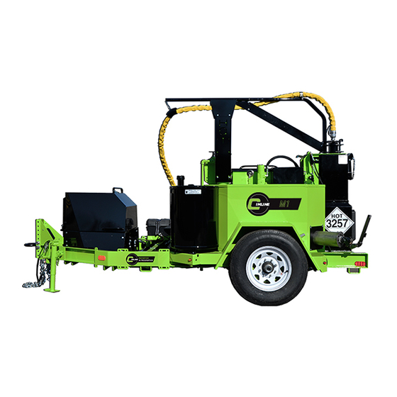
Page 9: M-Series Feature Overview
M-Series Feature Overview NOTE : This general outline will familiarize you with this machine, dependent on model, location and style and may vary with options installed. Read through the entire manual before putting this machine into operation. Main Control Panel: The main control panel is used to control the primary functions of the melter, including simple automated user controls for Off / Run / Clean Out / Cool Down as well as manual control of the sealant material pump direction and tank agitator. -
Page 10: M-Series Control Panels And Their Functions
M-Series Control Panels and Their Functions MAIN CONTROL PANEL: The Main Control Panel is used to operate the melter control system. Controls located on the outer cover are for operating in AUTO mode only. OFF: Shuts down power to the control panel and the pump, agitator and burner. RUN: Allows the preprogrammed controllers to turn on the pump, agitator, and burner. - Page 11 M-Series Control Panels and Their Functions DUAL PUMP AUXILIARY CONTROL PANEL (M4 DUAL ONLY): The dual pump auxiliary control panel is used to operate the secondary pump and hose controls. OFF: Shuts down power to the auxiliary control panel. Keep the auxiliary control panel in the “OFF”...
-
Page 12: M-Series Manual Sub Control Panel And Its Functions
M-Series Manual Sub Control Panel and Its Functions... - Page 13 HEAT TRANSFER OIL CONTROLLER: The control system on you CIMLINE melter has been factory set to not exceed the OEM heat transfer oil limits for maximum temperature. It is advised to only use heat transfer oil from CIMLINE.
-
Page 14: M-Series Start Up Procedure
M-Series Start Up Procedure LOAD FRESH SEALANT MATERIAL INTO TANK: All sealant material must be clean. Keep all foreign matter out of melting tank to avoid damage to pump and systems. 1) Open the material door (A) and place the block of sealant material (B) on the open door against the holder (C). - Page 15 M-Series Start Up Procedure 5. PREPARE HOSE AND WAND: When the (green) hose ready light (A) is illuminated. A) Unlock the boom (B) by raising and displacing the locking pin. The boom is free to swing now. B) Place the wand in the recirculation port (C) and pin the trigger.
-
Page 16: M-Series Clean Out/Shut Down Procedure
M-Series Clean Out / Shut Down Procedure 1. SET ROTARY SWITCH OUTSIDE CONTROL BOX TO “CLEAN OUT”: The clean out function on the control box will reverse the sealant material pump and begin to evacuate the wand, heated hose and internal plumbing of a majority of the sealant material and return it back to the sealant material tank. - Page 17 M4 Dual Hose Clean Out / Shut Down Procedure METHOD #1 1. SET AUXILIARY HOSE CONTROL PANEL SWITCH (A) TO “AUTO”: The clean out function on the auxiliary hose will run concurrently with the primary hose cleanout procedure on the main control box. Follow all instruction for the auxiliary hose as you would on the primary hose (as described on the previous page).
-
Page 18: M-Series Sealant Material Tank Capacity
M-Series Sealant Material Tank Capacity The amount of sealant material can be estimated by measuring the distance from the top of the tank to the sealant material. (When Material is cold) To maintain safe operation of trailer while in transport, WARNING do not fill tank more than 75% of total tank capacity. -
Page 19: M-Series Automatic Temperature Control Setting
OTHER MELTER NOTES: On a new CIMLINE Melter Applicator or a unit that has been idle for some time, it is recommended that you slowly raise the oil temperature to 250ºF (121°C) and hold there for approximately 20 to 30 minutes. This will help evaporate any water condensation that may be in the oil chamber. -
Page 20: M-Series Fluid And Components Specifications
Due to the dusty conditions that can be created by road work, it is essential to check the engine air cleaner element daily. Remove element and shake out the accumulated dust and dirt. Wipe out dirt from inside cover and from housing. Reference engine manual for washing instructions. CIMLINE recommends stocking replacement filters. -
Page 21: M-Series Heat Transfer Oil Specs
To insure maximum safety and performance, CIMLINE recommends you purchase your oil through CIMLINE directly. CIMLINE heat transfer oil can be ordered in 5 or 30 gallon (19L and 114L) bulk quantities and is also included when ordering a CIMLINE maintenance kit. PN 409185 (M1 & M2), PN 409186 (M4, M4 Dual and MA4). -
Page 22: Maintenance And Troubleshooting
M-Series Maintenance And Troubleshooting MAINTENANCE AND TROUBLESHOOTING: M-Series Maintenance Schedule ................23 M-Series Maintenance - Changing Heat Transfer Oil ..........24 M-Series Maintenance - Sealant Material Pump .............25 M-Series Maintenance - Sealant Material Plumbing ..........26 M-Series Maintenance - Recirculation Valve Timing ..........27 M-Series Maintenance - Hydraulic Oil Servicing .............28-29 M-Series Maintenance - Tank Burner ..............30-34 M-Series Maintenance - Trouble Shooting Guide ............35... -
Page 23: M-Series Maintenance Schedule
M-Series Maintenance Schedule Every Manual Every Every Every Every 500 Hrs. Maintenance Schedule / Operation Page 25 Hrs. 100 Hrs. 200 Hrs. Number Yearly Check engine fuel level (add if low) Check engine oil and heat transfer oil (add if low) 20/24 Check hydraulic oil (add if low) 20/28... -
Page 24: M-Series Maintenance - Changing Heat Transfer Oil
The melter operates at elevated temperatures which can cause WARNING burns. Be sure the heat transfer oil is cool before performing maintenance. Using oil that does not meet CIMLINE Heat Transfer Oil NOTICE specification is cause for a voided warranty. CHANGING/REPLACEMENT OF HEAT TRANSFER OIL: 1) Remove the dipstick (A) and the larger hex head cap (B) on the top of the expansion tank (C). -
Page 25: M-Series Maintenance - Sealant Material Pump
The material pump is sealed by a series of compressible fibrous braded graphite packing rings, If tightening does not reduce the leaking, replace these packing rings. Contact your CIMLINE dealer for packing ring kit and follow the instructions below to replace. -
Page 26: M-Series Maintenance - Sealant Material Plumbing
M-Series Maintenance - Sealant Material Plumbing Material Plumbing Its important to check the torque of the nuts on the plumbing flanges, check the torque of the nuts after the initial 8 hours of run time, then every 200 hours after that. Accessing Plumbing M1 and M2 A) Remove rear plumbing cover (A) by removing... -
Page 27: M-Series Maintenance - Recirculation Valve Timing
M-Series Maintenance - Recirculation Valve Timing SEALANT MATERIAL RECIRCULATION VALVE: The material sealant pumping system relies on a mechanical valve to direct the flow of material either to the application hose and wand or in recirculation mode back to the tank. This valve is operated by a hydraulic actuator and is connected to the recirculation valve shaft by a clamp and two set screws. -
Page 28: M-Series Maintenance - Hydraulic Oil Servicing
HYDRAULIC OIL: Use high quality Conoco MV32 or equivalent hydraulic oil. CIMLINE recommends that you do not mix oil brands. Mixing any oils (Engine oil, hydraulic oil, etc.) adversely affects each manufacturers formula. The maximum capacity of the hydraulic reserve tank is 33 gallons (125L). - Page 29 (B) into the tank while replacing the filter cup (A) into the return filter base. 9) Place a new filter cartridge (C), Cimline part number 170407, into the filter cup (A) and seat properly all the way into the cup.
-
Page 30: M-Series Maintenance - Tank Burner
C. Inspect the diesel supply system. All fittings should be leak-tight. D. Verify the nozzle is the one originally specified by CIMLINE and always replace the nozzle with one having the exact specifications from CIMLINE. - Page 31 M-Series Maintenance - Tank Burner TANK BURNER TROUBLESHOOTING: Oil burners that are designed for use on road maintenance equipment are built to take temperature extremes, vibration, and rough handling. When performing the following troubleshooting steps, we assume that the oil burner motor and ignition transformer operate continuously and the oil solenoid valve, which controls oil flow, is cycled by the equipment controls.
- Page 32 M-Series Maintenance - Tank Burner Igniter Maintenance: The igniter assembly does not require any adjustments beyond making sure the springs and the burner electrode rods make solid contact when the igniter is in the closed position. The sealing surfaces of the gaskets should be checked and replaced at the first signs of any damage or deterioration.
- Page 33 M-Series Maintenance - Tank Burner Primary Controller: The Beckett ADC tank burner motor is used to drive the blower and pump. The rotational speed of the motor is determined by the voltage supplied and the load placed on the motor. Pump pressure and air settings are the main factors affecting the motor load.
- Page 34 M-Series Maintenance - Tank Burner Bleeding The Fuel Supply Line (Older Melter Units): More recent CIMLINE Melters us a Clean-Cut Fuel Pump on the Beckett Burner units. These more modern fuel pumps are self priming and this process should not be needed.
-
Page 35: M-Series Maintenance - Trouble Shooting Guide
M-Series Trouble Shooting Guide Problem Cause Solution Fuse burned out Check 20A fuse at sub control panel Burner relay inoperative Check for 12VDC at relay Burner will not ignite Primary control fuse Check control switch fuse Thermocouple(s) inoperative Replace thermocouple(s) Fuse burned out Check 10A control switch fuse Sealant material not hot enough... -
Page 36: M-Series Melter Applicator Service Parts Kits
M-Series Service Parts Kits (Optional) M-Series Maintenance Kit Part #409185 for M1 and M2 and Maintenance Kit Part #409186 for M4, M4 Dual and MA4 Maintenance Kit Part #409185 Part # Description 403400 Burner Chamber Lining Kit 152487 Heat Chamber Insulation 170169 3”... - Page 37 M-Series Spare Parts Kit (Optional) M-Series Melter Spare Parts Kit Part #404695 PART # DESCRIPTION QTY. PART # DESCRIPTION QTY. 152105 Electric Eye 130384 Material Controller 200352 Burner Primary Control 130097 Thermocouple 130113 12V/30A Relay (Hose & Burner) 130505 240V/18A Ceramic Fuse 152399 Burner Coupling 152883 12V/10A Blade Fuse (Qty 5)
-
Page 38: Parts And Assembly Diagrams
M-Series Parts and Assembly Diagrams PARTS AND ASSEMBLY DIAGRAMS: M-Series Trailer Wiring Diagram and Parts ........... 39 M-Series Main Wiring Harness ............40-41 M-Series Control Panel Wiring Diagram and Parts ........ 42-45 M-Series Combustion Chamber Parts ..........46 M-Series Tank Burner Internal Wiring Diagram ........47 M-Series Tank Burner Parts .............. -
Page 39: M-Series Trailer Wiring Diagram And Parts
M-Series Trailer Wiring Diagram and Parts 60” Trailer Harness Cable PN 156025 Trailer Lights Junction box PN 130503 Front view of plug BRAKING NOTE: Brake controller is required on vehicle to activate the brakes on the trailer. TRAILER LIGHT COMPONENTS: Material Description Location 130360... -
Page 40: M-Series Main Wiring Harness
M-Series Main Wiring Harness Diagram Melter Component Harness - PN 130578 Tank Burner Wiring diagram - All Melters MAIN CONTROL PANEL LOFA (Engine Switch) Color Function White Hose A.C. Voltage Black Hose A.C. Voltage Red/Black Stripe Burner Power Battery (+) Battery White Burner Enable... - Page 41 M4 Dual Main Wiring Harness Diagram Battery M4 Dual Wand Generator Harness PN 130578 Wiring diagram # Color Function 1 White Hose A.C. Voltage 2 Black Hose A.C. Voltage Right Aux Control 4 Red Battery (+) Generator 8 Green Generator Excite M4 Dual Wand Splitter Harness PN 130947 Wiring diagram Harness...
-
Page 42: M-Series Control Panel Wiring Diagram And Parts
M-Series Control Panel Wiring Diagram... - Page 43 M-Series Control Panel Wiring Diagram AWG Wire Number Color Function Gauge White Hose AC Voltage Black Hose AC Voltage Red/Black Stripe Burner Power Battery (+) White Burner Enable Micro Panel Accessory Input Green/Yellow Stripe Battery (-) Green Generator Excite Accessory Relay Output Relay Panel Lug to Fuse Fuse to Relay Fuse to Burner Relay...
- Page 44 M-Series Control Panel Parts (130831) Part # Description Qty. 130122 Toggle Switch SPST 130222 12V 75A Relay 130113 12V 30A Relay 429735 Fuse Block 130624 Yellow LED Light 152119 18 Amp Slow Blow Fuse 130625 Green LED Light Terminal Strip 153870 Relay Base 200598...
- Page 45 M4 Dual Auxiliary Control Panel Parts Color Function Wire Gauge # PART # DESCRIPTION QTY. White Hose AC Voltage 1 153870 Relay Base Black Hose AC Voltage Orange TFC Inlet Terminal Strip DIN Orange TFC Outlet 3 200598 Heated Hose Controller Power 4PDT Toggle Switch On/Off/On Pink...
-
Page 46: M-Series Combustion Chamber Parts
Combustion Chamber Parts COMPLETE ASSEMBLY (ITEMS 1-11) - Part #404518 PART # DESCRIPTION QTY. 403400X Chamber Lining Kit 402898 Burner Mount 402893 Heat Chamber Skin 417041 Inspection Cover 152487 Insulation Heat Chamber 100125 Washer-Flat .31 100093 Washer - Split Lock .38 100092 Washer - Split Lock .31 100068... -
Page 47: M-Series Tank Burner Internal Wiring Diagram
Tank Burner Internal Wiring Diagram COLOR DESCRIPTION COLOR DESCRIPTION Brown Alarm To Controller Violet Fuel Valve Input Lead Violet Fuel Valve To Controller White Fuel Valve Ground Lead Black Fuel Valve Ground To Controller White Secondary Igniter Input Lead Wht/Blu Igniter To Controller Wht/Blu Primary Igniter Input Lead Black Igniter Ground To Controller... -
Page 48: M-Series Tank Burner Parts
Tank Burner Parts PART # DESCRIPTION PART # DESCRIPTION 152197 Tank Burner, Complete M1 & C1 153446 Burner Head Tube 404428 Tank Burner, Complete M2 152398 Air Inlet Guide 404388 Tank Burner, Complete M4 & MA4 152399 Coupling 153505 Square Plate, Gasket 152466 Blower Wheel 152191 Tank Burner Motor (Items #12 &... -
Page 49: M-Series Hydraulic Reservoir And Diesel Tank Parts
M-Series Hydraulic Reservoir and Diesel Tank Parts PART # DESCRIPTION 172618 Hydraulic Tank 309-074-004 Diesel Tank 172127 Return Filter Assembly (Non-Compressor) 170407 Element - Return Filter (Non-Compressor) 152044 Filler Cap Assembly 171631 Sight Gauge 172186 Suction Strainer 156463 Fuel Gauge / Cap 120743 Fuel Shut-off Valve 170169... -
Page 50: M-Series Hydraulic Manifold Parts And Schematic
M-Series Single Hose Hydraulic Manifold Parts Part # Description 172371 Hydraulic Manifold 171597 Gauge 172587 Relief Valve (Set at 800 PSI) 172226 Spool and Coil Kit for Material Pump 172224 Spool for Material Pump 172225 Coil for Material Pump (2 Required) 172589 Spool and Coil Kit for FC (Flow Control) 172557... - Page 51 M-Series Single Hose Hydraulic Schematic...
- Page 52 M4 Dual Hose Hydraulic Manifold Parts Part # Description 172371 Hydraulic Manifold 171597 Gauge 172587 Relief Valve (Set at 800 PSI) 172226 Spool and Coil Kit for Material Pump 172224 Spool for Material Pump 172225 Coil for Material Pump (2 Required) 172589 Spool and Coil Kit for FC (Flow Control) 172557...
- Page 53 M4 Dual Hose Hydraulic Schematic...
-
Page 54: M-Series Diesel Engine Components
M-Series Diesel Engine Components See the included engine manual for additional engine component diagrams and information. PART # DESCRIPTION PART # DESCRIPTION 425244 Plate, Engine Mount LH 406016 Generator Mounting Bracket 155143 Flexible Exhaust 156283 30A Alternator 156057 Hydraulic Pump(s) 155976 Exhaust Tube Weld 110947... - Page 55 M-Series Diesel Engine Components See the included engine manual for additional engine component diagrams and information. PART # DESCRIPTION PART # DESCRIPTION 111838 Engine 150212 Battery 26/26R-50-Wet 422167 Plate, Engine Mount RH 111111 Air Filter 100126 Washer - Flat .38 111337 Oil Filter 409037...
- Page 56 M4 Dual Hose Diesel Engine Components See the included engine manual for additional engine component diagrams and information. PART # DESCRIPTION PART # DESCRIPTION 425244 Plate, Engine Mount LH 406016 Generator Mounting Bracket 155143 Flexible Exhaust 156164 60A Alternator 155927 Hydraulic Pump(s) 155976 Exhaust Tube Weld...
- Page 57 M4 Dual Hose Diesel Engine Components See the included engine manual for additional engine component diagrams and information. PART # DESCRIPTION PART # DESCRIPTION 111838 Engine 111111 Air Filter 422167 Plate, Engine Mount RH 111337 Oil Filter 100126 Washer - Flat .38 130431 Generator 409037...
-
Page 58: M-Series Sealant Material Plumbing Parts
M1 and M2 Sealant Material Plumbing Parts... - Page 59 M1 and M2 Sealant Material Plumbing Parts PART # DESCRIPTION QTY. 430519 Plate, Valve Brace 430421 Plate - Backer 430167 Plate, Valve Brace 429818 Plate - Backer 429599 Plate - Pump 429584 Plate, Bearing Mount 409576 Flange Support Weld 409484 Flange Support Weld 409032 Valve Sub - Assembly...
- Page 60 M4 Sealant Material Plumbing Parts...
- Page 61 M4 Sealant Material Plumbing Parts PART # DESCRIPTION QTY. 430519 Plate, Valve Brace 430421 Plate - Backer 430167 Plate, Valve Brace 429818 Plate - Backer 429584 Plate, Bearing Mount 422053 Plate - Pump 409712 Valve Sub - Assembly, RH 409617 Outlet Adapter 409576 Flange Support Weld...
- Page 62 M4 Dual Hose Sealant Material Plumbing Parts DRIVER SIDE ASSEMBLY PASSENGER SIDE ASSEMBLY...
- Page 63 M4 Dual Hose Sealant Material Plumbing Parts PART # DESCRIPTION QTY. 430421 Plate - Backer 430167 Plate - Valve Brace 429818 Plate - Backer 429584 Plate - Bearing Mount 422053 Plate - Pump 409712 Valve Sub - Assembly RH 409617 Outlet Adapter 409576 Flange Support Weld...
-
Page 64: M-Series Sealant Wand Diagram And Parts
M-Series No Drip Sealant Wand PART # DESCRIPTION QTY. PART # DESCRIPTION QTY. 100017 HHCS .38 x 1.25 152058 Switch 100020 HHCS .38 X 2.00 155297 Spring 100126 Washer-Flat .38 155975 Sleeve w/Link 100169 Nut-Plastic Lock .38 171065 Swivel 100206 Nut-Hex .25 303-005-000 Handle Assembly 100207... - Page 65 M-Series Heated Wand PN 309-010-902 Part # DESCRIPTION 156431 Duckbill Valve 152058 Switch 407232 Swivel Tip 309-021-000 Valve Cover 309-015-000 Wand Cover 156430 Handle 309-022-000 Wand Assy 309-015-000 Switch Adapter 172697 O-Ring 156430 Handle 170635 Swivel 131060 Switch Harness, 50 in Long 131059 Heater Harness, 25 ft Long For use with 20’...
- Page 66 M-Series Legacy Sealant Wand Parts PART # DESCRIPTION QTY. PART # DESCRIPTION QTY. 429945 STUD 130323 SWITCH - MOMENTARY 427557 CLUTCH LEVER 130224 BOOT, SWITCH 427358 130155 CLEVIS KIT-.25-28 X .25 427116 SPRING GUARD 120560 WAND VALVE .75 IN 426987 SPACER 120412 PIPE-NIPPLE-CLOSE-.75 407872...
-
Page 67: M-Series Agitation System Diagram And Parts
M1 and M2 Agitation System Parts PART # DESCRIPTION QTY. PART # DESCRIPTION QTY. 110294 Key .38 X 2.00 LG 110294 Key .38 X 2.00 LG 170467 Motor - Agitation 170602 Motor - Agitation 170449 Load Adapter M 170449 Load Adapter M 416670 Agitator Motor Mount 416670... - Page 68 M4 Agitation System Parts PART # DESCRIPTION QTY. PART # DESCRIPTION QTY. 404327 Motor Mount 100126 Washer - Flat .38 170602 Motor - 45 CU IN 100093 Washer - Split-lock .38 111087 Sprocket 110294 Key .38 X 2.00 LG 111088 Sprocket 100006 HHCS .31 X 1.0...
-
Page 69: M-Series Miscellaneous Components And Parts
Cabinet Panel - RH 172618 Hydraulic Tank - Black 409116 Wand Cradle - Drip Tray 171631 Sight Gauge - 5 In. 427423 Plate - Cradle (2 Required) 130831S M Series Control Box 309-058-902 New Boom Update Kit 429900 Cover - Manifold Agitator Assembly... - Page 70 M-Series Miscellaneous Components and Parts PART # DESCRIPTION PART # DESCRIPTION 404341 Dipstick - Melter 100512 Muffler Clamp - 2 In. 152664 Anchor Shackle W/Pin 140330 Jack 5000 Lb. 429581 Pin - Engagement 130050 Switch - Breakaway 154308 Spring 111838 Engine Assembly 111861 Set Collar - .56 130166 Gauge - 0-160 PSI...
- Page 71 M4 / M4 Dual Miscellaneous Components and Parts PART # DESCRIPTION 409621 Cabinet Door - M4 409619 Cabinet Panel - RH - M4 409618 Cabinet Panel - LH - M4 153529 Rubber Pad 130944S Dual Heated Hose Control Box 420170 Cover - Agitator Bearing 429833 Plate - Manifold Mount...
-
Page 72: M-Series Optional Sealant Wand Attachments
Optional Sealant Wand Attachments PIVOTING SHOE 2-1/2” / 403137 2-1/2" Wide Band 3/4" NPT Inlet Open Shoe Design For Clear Visibility Of Material Pivoting Inlet Tube Maintains Contact With The Road SEALING DISC 3.5” / 403162 SEALING DISC 2.5”... - Page 73 This page intentionally left blank...
- Page 74 This page intentionally left blank...
- Page 76 2601 Niagara Lane · Plymouth, MN 55447 · (763) 557-1982 · (800) 328-3874 · Fax (763) 557-1971...
Need help?
Do you have a question about the M1 and is the answer not in the manual?
Questions and answers