Table of Contents
Advertisement
Quick Links
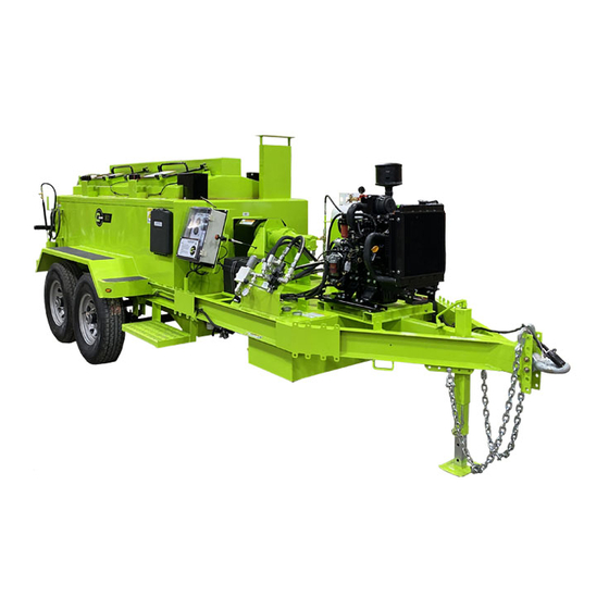
Mastic Extruder
Owner/Operator Manual
Due to continuous product development some of the details shown in this manual may differ from
your equipment. We reserve the right to change the contents of the manual without notification.
CIMLINE.COM
2601 Niagara Lane · Plymouth, MN 55447 · (763) 557-1982 · (877) 841-0848 · Fax (763) 557-1971
Part # 308-000-000
REV B 06/8/21
Advertisement
Chapters
Table of Contents
Troubleshooting

Related Manuals for CIMLINE ME3


Summary of Contents for CIMLINE ME3
- Page 1 Due to continuous product development some of the details shown in this manual may differ from your equipment. We reserve the right to change the contents of the manual without notification. CIMLINE.COM 2601 Niagara Lane · Plymouth, MN 55447 · (763) 557-1982 · (877) 841-0848 · Fax (763) 557-1971...
-
Page 2: Table Of Contents
MAINTENANCE AND TROUBLESHOOTING: ME3 Maintenance Schedule ..................23 ME3 Maintenance - Key Components ..............24 ME3 Maintenance - Changing Heat Transfer Oil ............25 ME3 Maintenance - Heat Transfer Oil Servicing ............26-27 ME3 Maintenance - Tank Burner ................28-31 ME3 Maintenance - Trouble Shooting Guide ............ -
Page 3: Serial Number, Model Number, Engine Number
____________________________ CONTACTING CIMLINE At Cimline, impressing the customer is one of our core values. We want to make sure you are covered for any general or technical questions you may have on your new CIMLINE equipment. Please use the following information to get the support you need if this manual does not provide the answers you are looking for. -
Page 4: Personal Safety, Signal Words In Manual
OPERATOR MUST READ AND UNDERSTAND ENTIRE OPERATORS MANUAL BEFORE PROCEEDING. THIS PAGE ONLY PROVIDES AN OVERVIEW OF SAFETY INFORMATION Personal Safety The melter operates at elevated temperature which can WARNING cause burns. Operator and anyone working in close proximity to hot materials must always wear protective clothing. Required clothing includes : Gloves with wristlets •... -
Page 5: Trailer Safety
Trailer Safety Operating this machine requires workers to perform work behind the trailer, it is critical to perform the work safely. Communication between the tow vehicle driver and worker is critical. Worker and tow vehicle driver must stay in communication, use an audible device or visual signals to communicate. -
Page 6: Wheel Specifications
Wheels Wheel Selection When specifying or replacing your trailer wheels it is important that the wheels, tires, and axles are properly matched. The following characteristics are extremely important and should be thoroughly checked when replacement wheels are considered: 1. Bolt Circle. Wheels have many bolt circle variations and some are so close that is could be possible to attach an inappropriate wheel that does not match the axle hub. - Page 7 Wheels Wheel Sizes Torque Sequence 14” - 15” - 16” - 16.5” x 6.75” 1st Stage 2nd Stage 3rd Stage NOTE: All torque in ft-lb 20-25 50-80 90-120 LUG TIGHTENING SEQUENCE CHART TIRES Prior to mounting tires onto wheels, be sure the rim size and contour are approved by the Tire and Rim Association Yearbook or the Tire Manufacturers Catalog in the United States and Recreational Vehicle Running Gear Certification - CSA CAN3 in Canada.
-
Page 8: Weights And Dimensions
Weight and Dimensions BASE WEIGHT 6500 lb (2954 kg) Length 220 in (559 cm) WEIGHT AND DIMENSIONS ARE FOR BASE UNIT WITHOUT OPTIONS WEIGHT LISTED DOES NOT INCLUDE MATERIAL WEIGHT. - Page 9 Weight and Dimensions Height: 75 in (191 cm) Width 86 in (214 cm) Mixing Tank Size Maximum Tank Sealant Capacity 350 Gallons 260 Gallons To maintain safe operation of trailer, WARNING do not fill tank more than 75% of tank size Product specification may change without notice.
-
Page 10: Replacement Labels
Replacement Labels Inspect your labels and replace any damaged. Contact your dealer to order replacement labels. Part #: 308-278-000... -
Page 11: Me3 Feature Overview
Melter Feature Overview NOTE : This general outline will only familiarize you with the machine. Read through the entire manual before putting this machine into operation. Propane Tank Mount: Propane Tank mount for heated tool box, handheld torch, and heated trough. Heated Tool Cabinet: Cabinet for mastic application tools that is heated with a propane burner. -
Page 12: Me3 Controls And Their Functions
Control Panels Main Control Panel The control panel is used to operate the melter control system. All controls are located within the cover. - Page 13 Inside the Main Control Panel box is a Sub Control Panel. See the next page for detailed explanation of use.
- Page 14 Heat Transfer Oil LED (Green): This LED indicates that the Heat Transfer Oil has reached the preset temperature. This indicates that you can turn the agitator on. Oil Temperature Controller: The controller for your CIMLINE ME3 melter has been factory set to run ISO Grade 68 heat transfer oil.
- Page 15 Sub Control Panel Controls and Their Functions...
-
Page 16: Me3 Start Up Procedure
Melter Start Up Load Material into Empty Tank All material must be clean. Keep all foreign matter out of melting tank. 1) Open the material door (a) and place the block of material (b) on the open door against the holder (c). 2) Push door to the closed position. - Page 17 Melter Start Up 3. MELTER PREPERATION A) Wait for the two indicator lights (GREEN lights) to turn on. B) Turn Agitator to the “HEAT UP” position. DO NOT OPERATE MACHINE IF DOOR ACTIVATED AGITATOR STOP IS NOT WORKING 4. SETTING AGITATOR SPEED Wait for material to reach desired temperature A) Ensure the Agitator is in the “Heat Up”...
-
Page 18: Me3 Cool Down/Shut Down Procedure
APPLYING MASTIC With Start Up procedure complete, you are ready to begin sealing A) Turn Agitator to the “DISPENSE” Position B) Open Material Gate at rear of machine. C) Let material flow onto heated chute. D) Scrape material from chute into Desired Tool. Cool Down Procedure A) Close the 2 propane needle valves (Near the Tool Box Heater and trough), 3 ball valves (2 at the propane tank and the 3rd at the back of the machine on the... -
Page 19: Me3 Automatic Temperature Control Setting
Modifying Sealant Temperature Control Settings The Sealant Temperature Control on your CIMLINE ME3 Melter has been factory set to run the most common types of mastics. These mastics have an application temperature of 380° F (193° C) With some mastics, it may be require a change to the controller to achieve the appropriate application temperature. -
Page 20: Me3 Fluid And Components Specs
YOU MUST CLARIFY with the supplier that the oil is to be used in a heat transfer system to avoid any potential problems. Oil is also available from CIMLINE in 5 and 30 gallon(19 and 114L) containers for ship-out. -
Page 21: Me3 Heat Transfer Oil Specs
NOTE: A dipstick (A) is provided for checking heat transfer oil level when cold. For oil level see Page 23. This is a petroleum based product. CIMLINE recommends that you do not mix oil brands. Mixing any oils (Engine oil, transmission fluid, etc.) adversely affects each manufacturers formula. -
Page 22: Maintenance And Troubleshooting
MAINTENANCE AND TROUBLESHOOTING: ME3 Maintenance - Schedule ................. 23 ME3 Maintenance - Key Components ..............24 ME3 Maintenance - Changing Heat Transfer Oil ............. 25 ME3 Maintenance - Hydraulic Oil Servicing ............26-27 ME3 Maintenance - Tank Burner ................28-31... -
Page 23: Me3 Maintenance Schedule
ME3 Maintenance - Schedule MAINTENANCE OPERATION DAILY HRS./ HRS. HRS. HRS. YEARLY CHECK ENGINE FUEL LEVEL CHECK ENGINE AND HEAT TRANSFER OIL CHECK HYDRAULIC OIL (ADD IF LOW) CHECK ENGINE AIR CLEANER GREASE AGITATOR BEARINGS CLEANOUT MATERIAL SYSTEM INSPECT AND CLEAN COOLING SYSTEM/RADIATOR... -
Page 24: Me3 Maintenance - Key Components
For more details about your engine please refer to the Engine Operator Maintenance Manual and Warranty provided with your Melter applicator. NOTE : When breaking in a new Melter, CIMLINE recommends running the engine for one hour with no load prior to actual use on the job. Air Cleaner Due to the dusty conditions that can be created by road work, it is essential to check the engine air cleaner element daily. -
Page 25: Me3 Maintenance - Changing Heat Transfer Oil
The melter operates at elevated temperatures which can cause WARNING burns. Be sure the heat transfer oil is cool before performing maintenance. Using oil that does not meet CIMLINE Heat Transfer Oil NOTICE specification is cause for a voided warranty. CHANGING/REPLACEMENT OF HEAT TRANSFER OIL: 1) Remove the dipstick (A) and fill cap (B) of the HTO tank. -
Page 26: Me3 Maintenance - Heat Transfer Oil Servicing
ME3 Maintenance - Hydraulic Oil Servicing SERVICING THE HYDRAULIC OIL: 1) Open the Hydraulic tank filler cap (A). 2) Unscrew and remove the Hydraulic tank drain plug from the bottom of the tank. Be prepared to capture nearly 15 gallons of fluid while the reservoir tank drains. - Page 27 HYDRAULIC OIL: Use high quality Conoco MV32 or equivalent hydraulic oil. CIMLINE recommends that you do not mix oil brands. Mixing any oils (Engine oil, hydraulic oil, etc.) adversely affects each manufacturers formula. The maximum capacity of the hydraulic reserve tank is 15 gallons (125L).
-
Page 28: Me3 Maintenance - Tank Burner
C. Inspect the diesel supply system. All fittings should be leak-tight. D. Verify the nozzle is the one originally specified by CIMLINE and always replace the nozzle with one having the exact specifications from CIMLINE. - Page 29 ME3 Maintenance - Tank Burner TANK BURNER TROUBLESHOOTING: Oil burners that are designed for use on road maintenance equipment are built to take temperature extremes, vibration, and rough handling. When performing the following troubleshooting steps, we assume that the oil burner motor and ignition transformer operate continuously and the oil solenoid valve, which controls oil flow, is cycled by the equipment controls.
- Page 30 ME3 Maintenance - Tank Burner Igniter Maintenance: The igniter assembly does not require any adjustments beyond making sure the springs and the burner electrode rods make solid contact when the igniter is in the closed position. The sealing surfaces of the gaskets should be checked and replaced at the first signs of any damage or deterioration.
- Page 31 ME3 Maintenance - Tank Burner Primary Controller: The Beckett ADC tank burner motor is used to drive the blower and pump. The rotational speed of the motor is determined by the voltage supplied and the load placed on the motor. Pump pressure and air settings are the main factors affecting the motor load.
-
Page 32: Me3 Maintenance - Trouble Shooting Guide
Trouble Shooting Guide Problem Cause Solution Fuse burned out. Check fuse. Burner relay inoperative Check for 12VDC at relay. Burner will not ignite Primary control fuse. Check fuse. Thermocouple(s) inoperative. Replace thermocouple(s). Fuse burned out. Check fuse. Sealant material not hot enough. Allow material to heat longer. - Page 33 PARTS AND ASSEMBLY DRAWINGS: ME3 Trailer Wiring Diagram and Parts ..............34 ME3 Main Wiring Harness ..................35 ME3 Control Panel Wiring Diagram and Parts ............36-38 ME3 Tank Burner Internal Wiring Diagram .............. 39 ME3 Oil Burner Parts ....................40 ME3 Agitation System Diagram and Parts ...............
-
Page 34: Me3 Trailer Wiring Diagram And Parts
Trailer Wiring Diagram... -
Page 35: Me3 Main Wiring Harness
Main Wiring Diagram ME3 MAIN HARNESS - PN 308-242-000 Wiring diagram DESCRIPTION COLOR 1 BURNER POWER RED/BLACK STRIPE 2 BATTERY (+) 3 BURNER ENABLE WHITE 4 MICROPANEL ASSC. PINK 5 BATTERY(-) GREEN/YELLOW STRIPE 30 BURNER ERROR BROWN MATERIAL MAIN CONTROL PANEL... -
Page 36: Me3 Control Panel Wiring Diagram And Parts
ME3 Control Panel Wiring Diagram... - Page 37 ME3 Control Panel Wiring Diagram NUMBER COLOR FUNCTION AWG WIRE GAUGE RED/BLACK STRIPE BURNER POWER RED/BLACK STRIPE BATTERY (+) WHITE BURNER ENABLE PINK MICROPANEL ACCESSORY INPUT GREEN/YELLOW STRIPE BATTERY (-) RED/BLACK STRIPE ACCS. RELAY OUTPUT RED/BLACK STRIPE RELAY PANEL LUG TO VOLTMETER...
- Page 38 Sealant Control Panel Part # Description 308-240-004 PLAT E- ME3 CONTROL PANEL 200597 CONTROLLER MATERIAL 200596 CONTROLLER OIL 130625 GREEN LED LIGHT 130831 FUSE BLOCK 130227 SWITCH SPDT 130222 PANEL RELAY 130113 BURNER RELAY 153870 RELAY BASE 130624 AMBER LED LIGHT...
-
Page 39: Me3 Tank Burner Internal Wiring Diagram
Burner Internal Wiring Diagram... -
Page 40: Me3 Tank Burner Parts
Oil Burner Parts List PART # DESCRIPTION 200666 BURNER ME3 156404 NOZZLE, 2.00 GPH X 80B 153505 SQUARE PLATE , GASKET 152191 MOTOR, OIL BURNER 155001 PUMP, OIL 152106 ELECTRODE ROD/INS ASSY 152128 GASKET, BURNER FLANGE 152173 IGNITION TRANSFORMER ASSY. -
Page 41: Me3 Agitation System Diagram And Parts
Agitation System Parts List Part # Description 100031 HHCS .5 X 1.25 100069 NUT-HEX .38 100072 5/8-11 HEX NUT 100126 WASHER-FLAST .38 100380 HHCS .38 X 4.5 PLN 100459 .625 FLAT WASHER 100858 HHCS 5/8 X 1 3/4 111946 GEARBOX 111947 COUPLING 2.25 DIA KEYED 111948... -
Page 42: Me3 Hydraulic Manifold Parts And Schematic
Mastic Hydraulic Manifold Components Part # Description QTY. 171597 PRESSURE GAUGE 172689 HYD SPEED CONTROL 172690 SOLENOID 172691 VALVE HOUSING 172692 SOLENOID HOUSING 172693 HYD SPINDLE 172694 3 WAY HYDRAULIC CONTROL VALVE 308-239-000 HYD HOSE KIT 12MP X 8FJS, STR 12MJ X 12MP, STR 8MJ X 8MP, STR 8FJ X 6MJ, STR... - Page 43 Mastic Hydraulic Manifold Components...
-
Page 44: Me3 Hydraulic Schematic And Lp Component Breakdown
Hydraulic Schematic... - Page 45 LP Component Breakdown Part # Description QTY. 308-238-000 LP HOSE KIT TEE, RUN, 4FP X 4MP X 4FP 120085 VALVE-BALL .25 NPT ELBOW, 90, 4MP X 4FP SWIVEL - 4MP X 4FP SWIVEL - 4MP X 4MP 40 LP HOSE 40”-7132-2534-101HY-4-4-101HY-4-4 115 LP HOSE 104”-7132-2534-101HY-4-4-101HY-4-4 1...
-
Page 46: Me3 Diesel Engine Components
Engine Components (See the included Engine Manual for additional engine component diagrams.) Part # Description 111951 ENGINE 3CJ1 ME3 308-252-004 PLATE - ME3 ENGINE MOUNT 153619 MUFFLER - COWL 172688 PUMP - HYD 200543 BATTER BOX 152047 SEALANT ISOLATOR 111108... - Page 47 Engine Components ENGINE MAINTENANCE KIT PART NUMBER 406599 PART # DESCRIPTION 172695 SPIN ON FILTER 170169 FUEL FILTER - BURNER 111457 FUEL FILTER - ENGINE 111111 AIR FILTER 111337 OIL FILTER...
-
Page 48: Me3 Miscellaneous Components And Parts
TROUGH WELDMENT 308-100-004 MATERIAL TANK DOOR 131035 FUEL CAP 308-247-004 BURNER TUBE 156392 LP ORIFICE 121163 NEEDLE VALVE 172694 3 WAY HYDRAULIC CONTROL VALVE 308-238-000 ME3 LP HOSE KIT 308-239-000 ME3 HYD HOSE KIT 308-275-000 AGITATOR STOP HARNESS * NOT SHOWN... - Page 49 Miscellaneous Parts...
-
Page 50: Me3 Mastic Tools
Optional Mastic Tools (A) Drag Box / 409577 Standard with every ME3 8 in Depth x 10 in Width Used to push or pull mastic along cracks (B) Flat Iron / 409578 Standard with every ME3 ... - Page 52 2601 Niagara Lane · Plymouth, MN 55447 · (763) 557-1982 · (800) 328-3874 · Fax (763) 557-1971...
Need help?
Do you have a question about the ME3 and is the answer not in the manual?
Questions and answers