Table of Contents
Advertisement
Quick Links
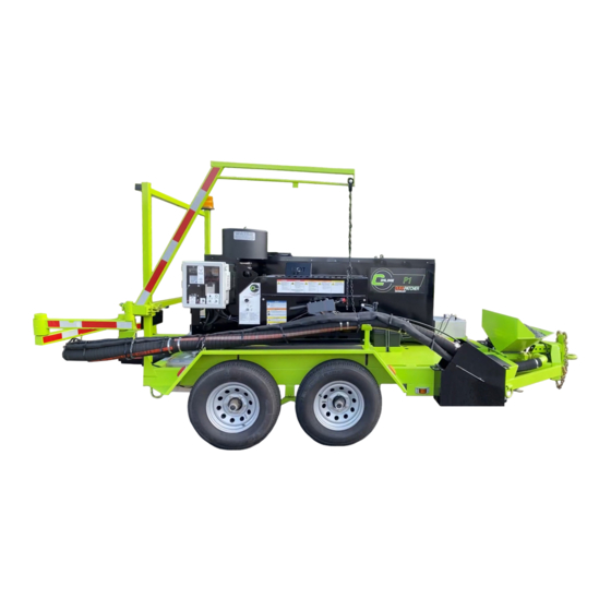
Spray Injection Road Repair
Owner/Operators Manual
Due to continuous product development some of the details shown in this manual may
differ from your equipment. We reserve the right to change the contents of the manual
without notification.
CIMLINE.COM
2601 Niagara Lane · Plymouth, MN 55447 · (763) 557-1982 · (800) 328-3874 · Fax (763) 557-1971
Part # 305-000-000
6/8/2021 Rev B
Advertisement
Table of Contents

Related Manuals for CIMLINE P1


Summary of Contents for CIMLINE P1
- Page 1 Due to continuous product development some of the details shown in this manual may differ from your equipment. We reserve the right to change the contents of the manual without notification. CIMLINE.COM 2601 Niagara Lane · Plymouth, MN 55447 · (763) 557-1982 · (800) 328-3874 · Fax (763) 557-1971 Part # 305-000-000...
- Page 3 WARNING Operating, servicing, and maintaining this machine can expose you to dust containing crystalline silica and engine exhaust which contains chemicals that are known to the State of California to cause cancer, birth defects, or other reproductive harm. For more information, go to www.P65Warnings.ca.gov.
-
Page 4: Table Of Contents
Table - Tank Cooling Times................. 20 P1 Feature Overview ......................21 P1 Operator Controls Overview ..................22 P1 Wand and Engine Controls Overview ................ 23 Operating the P1 ......................24-28 Before starting out ....................24 Engine startup procedures ..................25 Pump startup procedures .................. - Page 5 Table of Contents, continued... Control Panel ....................... 38-45 Modifying the heated hose controller ...............38 VFD (pump motor controller)..................39 Table - Hertz to RPM to GPM ...............39 Table - Common Fault Codes ..............39 VFD Controls ......................40 VFD Programming ....................40 VFD Parameter Flow Chart ..................41 Panel Wiring and Parts Diagram ................
-
Page 6: Shipping Papers And Information
This manual contains the basic information required to operate, maintain and repair the CIMLINE P1 Patcher you have purchased. The use of this manual insures accurate adjustments, operation and proper lubrication of your equipment. Please keep it handy. - Page 7 Contacting Cimline At Cimline, impressing the customer is one of our core values. We want to make sure you are covered for any general or technical questions you may have on your new Cimline equipment. Please use the following information to get the support you need if this manual does not provide the answers you are looking for.
-
Page 8: General Safety Overview
General Safety Overview Read Operators Manual thoroughly before operating NOTICE equipment You are in a position to ensure the safety of yourself and those around you. Lack of attention to safety can result in: accidents, personal injury, reduction in efficiency, and worst of all - loss of life. Watch for safety hazards and correct them promptly. -
Page 9: General Safety Considerations
General Operation Safety: 1) Perform a DOT pre-trip inspection, including but not limited to: a) Verifying that the hitch, chains, break-away switch and lights are properly connected to the tow vehicle. Refer to the vehicle manual safe towing guide b) Confirm the trailer brakes are properly adjusted and in good repair. c) Make sure all lights are in working order and reflectors are clean. -
Page 10: Personal Safety
Personal protective equipment (PPE) is to be worn by anyone checking or filling the emulsion tank. The air output from the P1 will produce dust and CAUTION flying debris. The operator and anyone working in close proximity to the nozzle must always wear PPE. -
Page 11: Trailer Safety And Stabilization Procedure
Trailer Safety Trailer may shift position without warning. Going WARNING under or on the trailer puts a person at risk of severe injury or death. ALWAYS use pin with swivel jack. NEVER place blocking under jack. NEVER use a damaged jack or pin. ALWAYS follow trailer stabilization procedure below before going under or on the trailer Operating this machine requires workers to perform work behind the trailer, it is critical to perform the work... -
Page 12: Wheels
Wheels Wheel Selection When specifying or replacing your trailer wheels it is important that the wheels, tires, and axles are properly matched. The following characteristics are extremely important and should be thoroughly checked when replacement wheels are considered: 1. Bolt Circle. Wheels have many bolt circle variations and some are so close that is could be possible to attach an inappropriate wheel that does not match the axle hub. - Page 13 Wheels Continued... Wheel Sizes Torque Sequence 14” - 15” - 16” - 16.5” x 6.75” 1st Stage 2nd Stage 3rd Stage NOTE: All torque in ft-lb 20-25 50-80 90-120 LUG TIGHTENING SEQUENCE CHART Tires Prior to mounting tires onto wheels, be sure the rim size and contour are approved by the Tire and Rim Association Yearbook or the Tire Manufacturers Catalog in the United States and Recreational Vehicle Running Gear Certification - CSA CAN3 in Canada.
-
Page 14: Hazards
ONLY trained professionals should preform live voltage testing DANGER POISONOUS GAS Using the gas powered P1 indoors WILL KILL YOU IN MINUTES. The engine exhaust contains carbon monoxide, a poisonous gas you cannot see or smell. NEVER use inside a home, garage, or confined space. - Page 15 CAUTION FLYING DEBRIES HAZARD Airborne debris may cause injuries or equipment damage ALWAYS wear eye protection such as a face shield or safety glasses to avoid eye injury from flying debris. STAY BACK from discharge nozzle, keep all body parts out of the air stream NEVER point discharge nozzle at a person or equipment.
- Page 16 WARNING FIRE AND EXPLOSION HAZARD Gasoline is an extremely flammable liquid and vapor. Negligence or improper care can cause fire. NEVER fuel a running or hot engine. ALWAYS fill gas tank outdoors. DO NOT overfill tank! Fill gas tank to bottom of filler neck only.
- Page 17 WARNING FIRE AND EXPLOSION HAZARD Hot asphalt and its fumes are extremely flammable. Negligence or improper care can cause fire. Keep asphalt material away from open flames, sparks, or incandescent materials DO NOT use cutback asphalt. DO NOT mix grades of asphalts. Hot asphalt can vaporize and ignite materials with lower a flashpoint ALWAYS keep a Class ABC Fire Extinguisher nearby and know its proper use.
-
Page 18: P1 Weights And Dimensions
P1 Weight and Dimensions Weight and Dimensions are for base unit without options Weight listed DOES NOT include material 92” 195” 88” HEIGHT WIDTH LENGTH BASE WEIGHT 92 INCHES 88 INCHES 195 INCHES 4800 Lbs. (2.34 m) (2.24 m) (4.95 m) -
Page 19: Capacity
P1 Emulsion Tank Prevent contact with hot material! Make sure the WARNING trailer is stabilized (page 11) and emulsion tank is level before opening the access hatch. Proper PPE must be worn when measuring or filling the tank. NEVER mix Cationic or Anionic emulsions without CAUTION properly cleaning the emulsion tank. -
Page 20: Heating The Emulsion
Heating the emulsion tank The standard P1 Patcher asphalt emulsion heating system uses a single 120 volt 13 amp (1450 watt) heater blanket that is thermostatically controlled. The blanket is designed to heat the tank and is not in direct contact with the emulsion. -
Page 21: P1 Feature Overview
P1 Feature Overview This general outline will familiarize you with the P1. NOTICE Locations and style and may vary with options installed. Read through the entire manual before putting this machine into operation. Temperature Gauge: Indicates the temperature of the emulsion in the tank... -
Page 22: P1 Operator Controls Overview
DANGER touch wiring or bare terminals without first locking out the machine (see page 32) This general outline will familiarize you with the P1. NOTICE Locations and style and may vary with options installed. Read through the entire manual before putting this machine into operation. -
Page 23: P1 Wand And Engine Controls Overview
P1 Wand and Engine Controls Overview This general outline will familiarize you with the P1. NOTICE Locations and style and may vary with options installed. Read through the entire manual before putting this machine into operation. Wand Controls Throttle : Controls engine and blower speed. -
Page 24: Operating The P1
Operating the P1 Before starting out 1. Read the engine hour meter and confirm no scheduled maintenance is due (see page 33) 2. Check material temperature gauge 3. Unplug the overnight heating blanket The trailer must be properly stabilized before going WARNING under or climbing onto machine. -
Page 25: Engine Startup Procedures
Engine start up procedure Use proper traffic control measures to prevent CAUTION collisions with the P1 or its workers 1. Set up traffic control to protect workers 2. From the control panel switch the Traffic Safety Lights to “ON” 3. Remove discharge nozzle from inside the catch tank and place on the outer rest 4. -
Page 26: Pump Startup Procedures
Operating the P1 continued... Pump start up procedure 1. Confirm that over 210 volts are available and the VFD is powered on and ready 2. Make sure the pump valve is set to solvent If valve was set to emulsion it indicates that the... -
Page 27: Cleanup
Cleanup 1. When you are finished with the P1 Patcher and are ready to store the unit overnight or any extended time, the emulsion supply line must be purged with diesel or other solvent. -
Page 28: Prepping For Next Day Operation
Summer / Hot Weather With the P1 Patcher parked and stabilized 1. Keep the machine unplugged to prevent over cooking the material 2. Keep the emulsion tank access port closed a. -
Page 29: Long Term Storage
Long Term Storage End of season 1. Empty and clean out the emulsion tank, pump, and lines. (see page 30) 2. Start the engine and run it for 20 minutes Empty the aggregate hopper, pipe, and hose during this time. Close the rock gate when finished. 1. -
Page 30: Emulsion Tank Cleanout Procedure
/ or unusable The Emulsion Tank on the P1 is designed to make use of its entire contents, leaving only material in the drain plumbing. Therefore before cleaning out the emulsion tank we recommend using as much of the material as possible during normal patching operations. -
Page 31: General Maintenance
General Maintenance Section... -
Page 32: General Maintenance Safety
General Maintenance Safety SAFETY INSTRUCTIONS Suggested Lockout Procedure 1) Announce lockout to other personnel 2) Stabilize trailer (see SAFETY INSTRUCTIONS on page 11) 3) Engine must be secured a) Turn ignition to off b) Remove key and place in pocket 4) De-energize controls a) Traffic Control Lights to off b) Controls power switch to off... -
Page 33: General Maintenance Chart
General Maintenance Chart... -
Page 34: General Maintenance Of Engine
General Maintenance of Engine This section is to be used in conjunction with the NOTICE Kohler Engine User Manual. Please thoroughly read the Kohler Manual and refer back to it with any questions on the engine. We recommend that you use a authentic Kohler parts for any general maintenance. Do not attempt to service or replace major engine components, including any items that require special timing or adjustment procedures. -
Page 35: Engine Cooling
With machine warmed up and material pump running tighten the 2 locknuts by a half turn allow pump to flow for a minute and examine for leakage. If leaking continues repeat in half turn increments until leaking stops. If tightening does not reduce the leaking replace packing rings, contact your CIMLINE dealer for Packing Kit... -
Page 36: General Maintenance Of The Blower
General Maintenance of Blower Blower Bearing Lubrication DO NOT use an electric or pneumatic grease gun as CAUTION they could force the grease in too rapidly and invert the seals. Use a NLGI #2 premium grade microgel grease or NOTICE aluminum complex grease with 250°F (121°C) service temperature and moisture resistance and good mechanical stability... -
Page 37: Belt Tightening Procedures
Belt Tightening Procedures The drive belts are under tension. Relieving that CAUTION tension may cause sudden movement and can lead to serious injury. Keep clear of the engine and generator when loosening the bolts. Improper tensioning on the belts can lead to power NOTICE loss and premature failure of the belts and pulleys Blower Belt... -
Page 38: Control Panel
Modifying the heated hose controller settings The Hose Temperature Control on your P1 Patcher has been factory set to run the most common types of emulsions at a temperature of 150° F (65°C). As you adjust your emulsion tank thermostat for different emulsions, you may require a change to the hose temperature controller to better match the emulsion tank temperature. -
Page 39: Vfd (Pump Motor Controller)
Control Panel VFD High voltage is present in the electrical circuits that WARNING are contained with in the control panel. Opening the cover for access will expose the worker to electrical shock The VFD is preprogramed. DO NOT try to reprogram CAUTION the VFD without contacting customer service first. -
Page 40: Vfd Controls
Control Panel VFD Controls From page 32 of Schneider Electric Altivar 12 User Manual VFD programing 1. To Enter press inward on center dial (7) a. Enter selects that parameter and brings you to the next sub level Pressing enter on ConF will bring you to a sub menu containing bFr and FULL among others. b. -
Page 41: Vfd Parameter Flow Chart
Control Panel VFD Settings VFD Parameter flow chart Below is a flow chart indicating the few parameters that are changed from the original factory settings. The end column indicates the proper values for the controls and electric pump motor This flow chart does not contain sub menus we do NOTICE not access or variables that are unedited. -
Page 42: Panel Wiring And Parts Diagram
Control Panel Wiring and Parts Diagram Motor Control Harness Generator Harness... - Page 43 LETTER LETTER 305-181-000 ENCLOSURE – COOLING MODIFICATION 131021 TERMINAL BLOCK – SINGLE – DIN MOUNT 305-172-000 LABEL – P1 CONTROL PANEL 131020 FUSE TERMINAL – DIN MOUNT 305-166-004 SHEET – GAUGE PANEL 131019 POWER RELAY – 200V - SPST NO 305-165-004 SHEET –...
-
Page 44: Motor Harness Diagram
Control Panel Motor Harness Diagram * REFER TO PAGE 43 FOR WIRE NUMBER DETAILS HEATED HOSE CONNECTION HEATED HOSE THERMOSTAT CONNECTION WAND CONTROLS WIRES SEE PAGE 46 PUMP MOTOR... -
Page 45: Generator Harness Diagram
Control Panel Generator Harness Diagram * REFER TO PAGE 43 FOR WIRE NUMBER DETAILS REGULATOR GENERATOR ENGINE GROUND STARTER BRAKES WIRE STROBE LIGHT WIRE SEE PAGE 44 SEE PAGE 44 IGNITION SWITCH P/N 111068 BATTERY POSITIVE TO STARTER NEGATIVE TO ENGINE GROUND IGNITION WIRING P/N 111217... -
Page 46: Wand Wiring Diagram
Wand Wiring Diagram Wire bundle from control panel (see page 44 for wire information) Where routes to: Horn Ground Actuator Wire bundle Retraction Limit Switch Actuator Black Wire 305-163-000 Extension Limit Switch (See page 47 for wire Horn Positive information) Optional Nozzle Heater Connect the optional nozzle heater wires to the terminals on the Open / Closed switch where... -
Page 47: Actuator Wiring Diagram
Actuator Wiring Diagram Part Number 305-163-000 Limit Switch Assembly Extension Limit Switch Retraction Limit Switch Actuator Wand Control Horn... -
Page 48: General Maintenance Of Rock Gate
General Maintenance of the Rock Gate No maintenance is required on the actuator. DO NOT NOTICE attempt to repair or service the actuator as this will void the manufactures warranty. The “clicking” sound from the actuator is the overload clutch protecting it from damage. Constant NOTICE engagement of the overload clutch will shorten the life of the actuator. -
Page 49: Setting Limit Switches
General Maintenance of the Rock Gate, Continued… Setting the limit switches The rock gate moves quickly with a lot of force. Use WARNING extreme caution and keep clear of the sliding gate when preforming maintenance that requires the actuator to be active. 1. -
Page 50: Actuator Circuit Design
General Maintenance of the Rock Gate, Continued… Actuator Circuit Design The design of the circuit allows the actuator to only move in the opposite direction of an switched “Off” limit switch Actuator Function a. Apply positive 12 VDC to red wire on actuator for extension (closes gate) b. -
Page 51: Trailer Wiring For Brakes And Lights
Trailer Wiring for Brakes and Lights... -
Page 52: Parts Section
Parts Section... -
Page 53: Engine Parts
Engine Parts Top Level 305-015-004... -
Page 54: Sub Assembly 305-028-004
Engine Parts, continued… Sub Assembly 305-028-004... -
Page 55: Engine Service Parts
Engine Parts, continued… Sub Assembly 305-028-004 Engine Service Parts... -
Page 56: Pump Assembly
Pump Assembly 305-018-004... -
Page 57: Axle Assembly
Axle Assembly... -
Page 58: Aggregate Plumbing Assembly
Aggregate Plumbing Assembly... - Page 59 Aggregate Plumbing Assembly PART # DESCRIPTION QTY. 407832 NOZZLE WELDMENT 2 305-026-004 WAND ASSEMBLY 155218 HOSE "A" SECTION 120862 CLAMP 3-1/2 TO 4-1/2 426760 TUBE, CONNECTOR 155340 BLOWER FILTER ASSEMBLY 155339 BLOWER AIR FILTER 155341 PREFILTER - BLOWER 155219 HOSE "B" SECTION 8 305-025-000 HEATED EMULSION HOSE 101261 U BOLT - 4"...
-
Page 60: Boom Arm Assembly
Boom Arm Assembly ITEM PART NUMBER DESCRIPTION 408411 BOOM ARM, FIRST SECTION 408430 BOOM ARM, FORTH SECTION 405623 BOOM ARM, SECOND SECTION 405624 BOOM ARM, THIRD SECTION 155446 ROLLER, YOKE 172079 SEAL, 3-3/8 OD X 2.01 ID 154433 2" RACE 111511 ROLLER BEARING 1.75 ID 423444... -
Page 61: Wand Assembly
131011 THROTTLE CABLE - SOLID CORE 131010 POTENTIOMETER – 10K 131009 ROCK SWITCH 130561 HORN SWITCH 131014 EMULSION SWITCH 100169 NUT-PLASTIC LOCK .38 100126 WASHER - FLAT .38 100017 HHCS .38 X 1.25 100017 P1 WAND CONTROLS LABEL 161861 CLAMPS... -
Page 62: Rock Gate Actuator Assembly
Rock Gate Actuator Assembly * Gate Guard 305-159-004 not shown for clarity purposes... -
Page 63: Miscellaneous Components And Parts
Miscellaneous Components and Parts... - Page 64 PART # DESCRIPTION QTY. KEEP HANDS OFF WARNING LABEL 409722 FUEL TANK 305-179-000 UNLEADED FUEL ONLY DECAL 161860 P1 BRAND DECAL MANHOLE BREATHER VENT 120971 2” PIPE PLUG 130592 THERMOMETER WITH 5” FACE 131001 FLAT MOUNT AMBER LED STROBE LIGHT...
- Page 65 Miscellaneous Components and Parts...
-
Page 66: Replacement Safety Labels (Free Replacement)
Replacement Safety Labels Inspect your labels and replace any damaged. Safety labels replaced free of charge. Contact your dealer to order replacement labels. Operators Protection Decal Dangerous Hazard Decal 305-170-000 305-171-000 Splash and Burn Warning Decal 305-180-000... -
Page 67: Replacement Labels
Replacement Labels Inspect your labels and replace any damaged. Contact your dealer to order replacement labels. Wand Control Label 161861 P1 Decal 161860... - Page 68 Replacement Labels Inspect your labels and replace any damaged. Contact your dealer to order replacement labels. Control Panel Decals 305-170-000 Engine Controls Decal Fuel Type Labels 305-178-000 305-179-000 Pump Valve Decal 305-178-000...
-
Page 69: Tailgate Discharge Box
Tailgate Discharge Box Assembly... -
Page 70: Tailgate Cutout And Welding Details
Tailgate Mounting Instructions... -
Page 71: Tailgate Hose Length And Alignment
Tailgate Hose Length and Alignment... -
Page 72: Optional Arrow Board Assembly
Optional Arrow Board Assembly... -
Page 73: Trouble Shooting Section
Trouble Shooting Section... -
Page 74: Engine
Trouble Shooting the Engine... -
Page 75: Rock Gate
Trouble Shooting the Rock Gate Issue Causes Solution No Movement No power to actuator 1. Confirm control panel power switch is “ON” 2. Check 30 amp fuse in the control panel box 3. Check to see if the battery is dead / dying 4. -
Page 76: Emulsion Pump
Trouble shooting pump start up Issue Causes Solution Make sure Control is switched to “ON” Voltage is reading over 210 volts on the gauge Check that the breakers are ON and not tripped. Red means live current (on) VFD not sending ... - Page 77 Trouble shooting pump start up, continued... Issue Causes Solution 1. Confirm solvent tank is full and lines are connected 2. Switch pump valve to solvent 3. Heat hose to material application temp 4. Turn the emulsion flow rate to max and run the pump for 30 seconds 5.
- Page 79 Cimline, Inc. P1 Spray Patcher Product Warranty 1. Limited Warranty: For one (1) year from the purchase date Cimline warrants to the original purchaser that the goods purchased are free from defects in material or workmanship with the following exceptions: 2.
- Page 80 2601 Niagara Lane · Plymouth, MN 55447 · (763) 557-1982 · (800) 328-3874 · Fax (763) 557-1971...
Need help?
Do you have a question about the P1 and is the answer not in the manual?
Questions and answers