Table of Contents
Advertisement
Operation &
Maintenance Manual
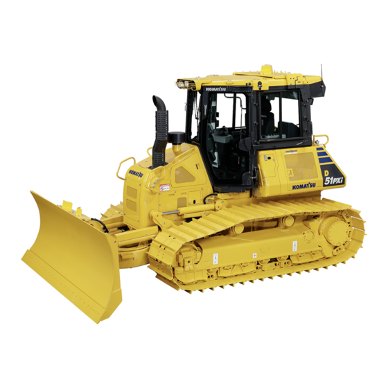
D51EXi
D51PXi
BULLDOZER
SERIAL NUMBER
D51EXi-24 - 10001
D51PXi-24 - 10001
WARNING
Unsafe use of this machine may cause serious injury or
death. Operators and maintenance personnel must read
this manual before operating or maintaining this
machine. This manual should be kept inside the cab for
reference and periodically reviewed by all personnel who
will come into contact with the machine.
-24
-24
and up
and up
ORIGINAL INSTRUCTIONS
EENAM03570
Advertisement
Chapters
Table of Contents

Related Manuals for Komatsu D51PXi-24


Summary of Contents for Komatsu D51PXi-24
- Page 1 Operation & EENAM03570 Maintenance Manual D51EXi D51PXi BULLDOZER SERIAL NUMBER D51EXi-24 - 10001 and up D51PXi-24 - 10001 and up WARNING Unsafe use of this machine may cause serious injury or ORIGINAL INSTRUCTIONS death. Operators and maintenance personnel must read this manual before operating or maintaining this machine.
- Page 3 Komatsu or Ko- matsu approved rebuilt parts or assemblies or others parts of equivalent quality, and that the engine be serviced by an authorized Komatsu distribu- tor. Failure to follow these recommendations could result in ineffective serv- ice, damage to the product or safety risks (including personal injury or death).
- Page 4 Before reading this manual, read the Operation and Maintenance Manual of standard machine (D51EX-24, D51PX-24). This manual describes only the special device or function for D51EXI-24 and D51PXI-24. For the other part than described in this manual, see the Operation and Maintenance Manual of standard machine.
-
Page 5: Safety Information
FOREWORD SAFETY INFORMATION SAFETY INFORMATION To enable you to use the machine safely, and to prevent personal injury to operators, service personnel or by- standers, the precautions and warnings included in this manual and the safety signs attached to the machine must always be observed. -
Page 6: Introduction
Use it at a place under the open sky where has no obstacle. • Base station For the usable the base station, consult your Komatsu distributor in advance. • Operation information data Project file is necessary, which contains the data necessary for “intelligent Machine Control” such as the design surface, base point, etc. -
Page 7: Table Of Contents
FOREWORD TABLE OF CONTENTS TABLE OF CONTENTS FOREWORD..............................1-1 READ THIS MANUAL ..........................1-2 SAFETY INFORMATION .......................... 1-3 INTRODUCTION ............................1-4 intelligent Machine Control ......................... 1-4 MACHINE FEATURES........................1-4 SAFETY................................2-1 GENERAL PRECAUTIONS COMMON TO OPERATION AND MAINTENANCE ........2-2 PRECAUTIONS WHEN GETTING ON OR OFF MACHINE............... - Page 8 METHOD FOR ADJUSTING CUT/FILL OFFSETS ................4-94 METHOD FOR CHANGING GRADE INDICATOR DISPLAY............4-94 METHOD FOR CHANGING DISPLAY OF LIGHT BAR..............4-96 OPERATION USING POP-UP MENU ....................4-96 SPECIFICATIONS ............................5-1 SPECIFICATIONS ............................ 5-2 SPECIFICATIONS: D51EXI-24 ......................5-2 SPECIFICATIONS: D51PXI-24 ......................5-2 INDEX................................6-1...
-
Page 9: Safety
SAFETY This section describes cautions which are necessary to provide the efficient operation with “intelligent Machine Control”. Please follow the instructions described in the Operation and Maintenance Manual for the standard machine for safety information of the whole ma- chine. -
Page 10: General Precautions Common To Operation And Maintenance
GENERAL PRECAUTIONS COMMON TO OPERATION AND MAINTE- NANCE SAFETY GENERAL PRECAUTIONS COMMON TO OPERATION AND MAINTENANCE Mistakes in operation, inspection, or maintenance may result in serious personal injury or death. Before per- forming operation, inspection, or maintenance, always read “SAFETY”, Operation and Maintenance Manual of standard machines and this manual carefully and obey the warnings. - Page 11 GENERAL PRECAUTIONS COMMON TO OPERATION AND MAINTE- SAFETY NANCE While the automatic control of blade is in operation, do not release your hand from the blade control lever, so that you can avoid the danger immediately if any. • When performing the inspection, maintenance, moving and loading/unloading on the trailer etc., i.e. other operation than the operation by “intelligent Machine Control”...
-
Page 12: Precautions For Operation
PRECAUTIONS FOR OPERATION SAFETY PRECAUTIONS FOR OPERATION START ENGINE IN COLD WEATHER • If the work equipment is operated without sufficient warming-up operation of the machine, response of the work equipment to movement of the control lever will be slow, and the work equipment may not respond as the operator intends, so always perform the warming-up operation. -
Page 13: Precautions For Maintenance
• If the GNSS antenna contacts with obstacles during operation or traveling, and it has to be checked and replaced, ask your Komatsu distributor. • There is a danger of falling or tipping over that can lead to serious personal injury or death. Do not get on... -
Page 15: Operation
OPERATION This section describes cautions which are necessary to provide the efficient operation with “intelligent Machine Control”. Please follow the instructions described in the Operation and Maintenance Manual for the standard machine for operation information of the whole ma- chine. -
Page 16: General View
GENERAL VIEW OPERATION GENERAL VIEW MACHINE EQUIPMENT NAME (1) Blade angle cylinder (with stroke sensor) (4) Blade tilt cylinder (with stroke sensor) (2) GNSS antenna (5) Blade lift cylinder (with stroke sensor) (3) Radio antenna MACHINE OUTSIDE EQUIPMENT NAME (1) GNSS satellite (GPS) (3) Base station (2) GNSS satellite (GLONASS) -
Page 17: Controls And Gauges Names
OPERATION GENERAL VIEW CONTROLS AND GAUGES NAMES (1) Control box (6) Cut/Fill offsets switch (Up) (2) Auto/Manual switch (7) Cut/Fill offsets switch (Down) (3) ICT sensor controller (inside the cover) (8) Back grade mode switch (4) GNSS receiver (inside the cover) (9) Network modem (if equipped) (5) GNSS radio device... - Page 18 GENERAL VIEW OPERATION CONTROL BOX NAME (1) Elevation control key (12) Toggle As-built mode (2) Cut/Fill offsets (13) iB logo key (3) Left window (14) Zoom in key (4) Main window (15) Zoom out key (5) Take a topo shot (16) Toggle main view (6) Blade load selection (17) Right window...
-
Page 19: Explanation Of Components
OPERATION EXPLANATION OF COMPONENTS EXPLANATION OF COMPONENTS The following is an explanation of devices necessary to operate the machine. To perform suitable operations correctly and safely, it is important to completely understand methods of operat- ing the equipment, and the meanings of the displays. intelligent Machine Control SYSTEM CONTROL BOX WARNING... - Page 20 When using the network modem, Komatsu recommends using Komatsu genuine network modem anten- na (option). If other antenna than Komatsu genuine part is used, it may not be complied with the regulations in the country or area where the machine is used. This is because the network modem is a wireless device which uses radio wave.
- Page 21 OPERATION EXPLANATION OF COMPONENTS How each state LED works For the questions about the communication, consult your Ko- matsu distributor. Display of the power supply state LED (1) Lighting color State Green Not lit Display of the communication state LED (2) Lighting color State Not lit...
- Page 22 EXPLANATION OF COMPONENTS OPERATION Auto/Manual switch is used for turning on or off the blade auto- matic control. Auto/Manual switch is located on the blade control lever. When turning on the blade automatic control Place the work equipment lock lever in FREE position (F), and press Auto/Manual switch once.
- Page 23 OPERATION EXPLANATION OF COMPONENTS When turning off the blade automatic control While the blade automatic control is on, press Auto/Manual switch once. The blade automatic control is turned off. The blade automatic control is turned off as well when the work equipment lock lever is placed in LOCK position (L).
- Page 24 EXPLANATION OF COMPONENTS OPERATION When the blade automatic control is automatically turned off In the following conditions, even if Auto/Manual switch is not pressed, the blade automatic control is automatically turned off. • When the machine is stopped for 30 seconds or more •...
- Page 25 OPERATION EXPLANATION OF COMPONENTS BACK GRADE MODE SWITCH Press the back grade mode switch, and select on or off of the back grade mode. The back grade mode switch is located on the right side of the blade control lever. When turning on the back grade mode Press the back grade mode switch once when blade automatic control is turned on (Control box displays “AUTO”).
- Page 26 EXPLANATION OF COMPONENTS OPERATION While the blade automatic control is OFF (“AUTO” is not dis- played on the control box screen), even if you press the back grade mode switch, it does not work. When turning off the back grade mode Press the back grade mode switch once while the back grade mode is turned on.
- Page 27 GNSS radio device is used to receive radio waves from the base station. Install GNSS radio device suitable for the radio specification of the base station. For usable GNSS radio device, consult your Komatsu distributor in advance. For details of handling GNSS radio device, see the instruction manual of GNSS radio device.
- Page 28 EXPLANATION OF COMPONENTS OPERATION GNSS RECEIVER (1) Radio antenna connecting point Machine body harness connecting point (DRC26-40P(B)) (2) GNSS antenna connecting point (5) GNSS satellite capturing display LED Machine body harness connecting point (DRC26-40P(A)) GNSS satellite capturing display LED (5) indicates the number of GNSS satellites by color and number of flash- •...
-
Page 29: Other Equipment
OPERATION EXPLANATION OF COMPONENTS OTHER EQUIPMENT LUNCH BOX FIXING BELT This is the place for lunch box. Fix the lunch box with belt. This can be used for other things than lunch box. Make efficient use of this. 3-15... -
Page 30: Machine Operations And Controls
3 seconds when turning the starting switch to ON posi- tion. If it does not light up, it may be defective such as open cir- cuit. Ask your Komatsu distributor for repair. Press power supply ON switch (green) to turn on the con- trol box power. REMARK... -
Page 31: Operations And Checks After Starting Engine
For details, see “METHOD FOR CONFIGURING RADIOS”. • If the starting switch is kept in OFF position (A), “slope control key” (2) is red and “Komatsu controller not connected!” is displayed. Turn the starting switch to ON position (B), check that “slope control key” (2) changes to green color, and proceed to the next step. - Page 32 MACHINE OPERATIONS AND CONTROLS OPERATION The message of “Cylinder Sensor Reset Request!” is dis- played on the control box screen. “Lift cylinder”, “Tilt cylinder”, or “Angle cylinder” is dis- played in the message. Reset the stroke end of the dis- played cylinder.
-
Page 33: Method For Stopping Engine
OPERATION MACHINE OPERATIONS AND CONTROLS Place the blade control lever to left TILT position (E) to op- erate it to the stroke end, and then keep it for 2 seconds or more. Check the message on the control box screen. When “Tilt cylinder”... - Page 34 MACHINE OPERATIONS AND CONTROLS OPERATION Press Auto/Manual switch once to turn off the blade auto- matic control. Check that “AUTO” on the control box screen goes out. Set the blade control lever to LOWER position (a) and low- er the blade to the ground. Press power supply OFF switch (red) to turn off the control box power.
-
Page 35: Method For Using Automatic Blade Control
Resetting is not necessary unless the settings of GNSS radio device and the base station are changed. REMARK Install GNSS radio device suitable for the radio specification of the base station. For the usable GNSS radio device, consult your Komatsu distributor in advance. Set the base station and turn on the power supply. 3-21... - Page 36 MACHINE OPERATIONS AND CONTROLS OPERATION Press power supply ON switch (green) to turn on the con- trol box power. Starting switch of the machine can be turned off. On the control box screen, press “iB logo key” and display the main menu. On “Tools”...
- Page 37 OPERATION MACHINE OPERATIONS AND CONTROLS INPUT PITCHING ROD LENGTH The length of pitching rod must be inputted when the blade edge has been adjusted. Measure the length of pitching rod and input it. Finishing accuracy of the blade automatic control is decreased if the machine is operated with the pitching rod of wrong length.
- Page 38 MACHINE OPERATIONS AND CONTROLS OPERATION Turn on the power supply of the control box. It does not matter if power supply of the base station and starting switch of the machine are turned off. Press “iB logo key” on the control box screen, and display the main menu.
- Page 39 OPERATION MACHINE OPERATIONS AND CONTROLS Turn on the power supply of the control box. It does not matter if power supply of the base station and starting switch of the machine are turned off. Press “iB logo key” on the control box screen, and display the main menu.
- Page 40 MACHINE OPERATIONS AND CONTROLS OPERATION CHECK BLADE ELEVATION, ADJUST For the automatic control of the blade, the position information of GNSS satellite is used. The position informa- tion of GNSS satellite contains the error, and the height varies up and down depending on the day or time. In order to minimize the deterioration of finishing accuracy by the error, check and adjust the blade elevation at least once a day before starting operation.
- Page 41 OPERATION MACHINE OPERATIONS AND CONTROLS 13. On “Position Check” screen, select the position of blade matched with the base point. • When matched with the left blade edge: “Blade: Left” • When matched with the right blade edge: “Blade: Right” 14.
- Page 42 MACHINE OPERATIONS AND CONTROLS OPERATION 19. After the engine stops, turn the starting switch to ON posi- tion (B) again. 20. Measure the height from the base point to the blade edge, add this value to the elevation of the base point. Check that the total value is equal to the elevation recognized by the machine in the step 14.
- Page 43 OPERATION MACHINE OPERATIONS AND CONTROLS SELECT ACTIVE FILE Before starting the automatic control of blade, select the design surface to use. For the method of selecting the design surface, see “ACTIVE FILE”. HANDLE AUTOMATIC BLADE CONTROL METHOD FOR ACTIVATING AUTOMATIC BLADE CONTROL Press Auto/Manual switch to turn off the blade automatic control.
- Page 44 MACHINE OPERATIONS AND CONTROLS OPERATION Move the blade control lever to LOWER direction (C) once and return it to NEUTRAL position (B). The blade automatically lowers to the design surface or height of the ground where the track contacts. REMARK •...
- Page 45 OPERATION MACHINE OPERATIONS AND CONTROLS When the operator stops lever operation and return the lever to NEUTRAL position, the blade automatic control restarts. Operation of angle switch (1) is independent from the blade au- tomatic control. While the blade automatic control is in opera- tion, operator can angle the blade to change the dumping di- rection of soil.
- Page 46 MACHINE OPERATIONS AND CONTROLS OPERATION HANDLE BACK GRADE MODE Press Auto/Manual switch to turn off the blade automatic control. When the blade automatic control is turned on, “AUTO” is displayed on the control box screen. Press the back grade mode switch once. After the buzzer sounds “peep”...
- Page 47 OPERATION MACHINE OPERATIONS AND CONTROLS LED of the back grade mode switch lights up, and the back grade mode indicator is displayed at the top of “AUTO” on the control box screen. While the back grade mode is turned on, when the joystick (steering, directional and gear shift lever) is set to reverse posi- tion (R), the blade automatic control operates as well similarly to when the lever is set to FORWARD position (F).
- Page 48 MACHINE OPERATIONS AND CONTROLS OPERATION When turning on the back grade mode again, press Auto/ Manual switch (1), turn on the blade automatic control, and press back grade mode switch (2). The back grade mode is turned on. DEACTIVATE AUTOMATIC BLADE CONTROL Stop the machine or set the joystick (steering, directional and gear shift lever) to NEUTRAL position (N).
- Page 49 OPERATION MACHINE OPERATIONS AND CONTROLS The blade automatic control is turned off as well when the work equipment lock lever is placed in LOCK position (L). When the blade automatic control is turned off, “AUTO” goes out from the control box screen. When the blade automatic control is switched from on to off, pop-up message “Auto Control Disengaged!”...
- Page 50 MACHINE OPERATIONS AND CONTROLS OPERATION When the blade automatic control is automatically turned off In the following conditions, even if Auto/Manual switch is not pressed, the blade automatic control is automatically turned off. • When the machine is stopped for 30 seconds or more •...
- Page 51 OPERATION MACHINE OPERATIONS AND CONTROLS Dozing mode Type of operation (A) Cutting & Carry Normal operation Effective dozing operation (Short (B) Cutting range cutting method) Spreading operation of piled soil high- (C) Spreading er than the blade height Operation to finish uneven ground, flat (D) Simple Grading ground, or slope by traveling along or across the slope...
- Page 52 MACHINE OPERATIONS AND CONTROLS OPERATION REMARK When the dozing mode is set to “Simple Grading”, the control by blade load is not performed, so the setting of the blade load mode cannot be done. SET SCRAPING DEPTH FROM CURRENT DRAWING You can set scraping depth quickly on the basis of the current drawing by using the matching function.
- Page 53 OPERATION MACHINE OPERATIONS AND CONTROLS On “Adjust elevation” screen, press “Ok” (3). The screen returns to the main window. On “elevation control key”, “Cut/Fill offset” (4) (value input in step 4) and “Cut/Fill reading” (5) (distance from the blade edge to the design surface) are displayed. SMOOTH START When the operation started with automatic control of blade, operation is controlled so that the shape after doz- ing is smooth and cutting shape is the same as preset.
- Page 54 MACHINE OPERATIONS AND CONTROLS OPERATION (S) Current surface (B) Smooth Start enabled (for “Cutting”) (T) Design surface (C) Smooth Start enabled (for “Cutting & Carry” and “Spreading”) (A) Smooth Start disabled CHANGE BLADE LOWER EDGE POSITION IN CUTTING IN When the machine cuts in with Smooth Start enabled, the blade lower edge height is usually the height of ground with which the track is in contact.
- Page 55 OPERATION MACHINE OPERATIONS AND CONTROLS If you perform this operation while there is no piled soil in front of the machine, the blade stops in air and is held at that position. In this case, place the joystick (steering, directional and gear shift lever) in NEUTRAL position, and restart the operation.
- Page 56 MACHINE OPERATIONS AND CONTROLS OPERATION METHOD FOR ADJUSTING GAIN OF AUTOMATIC BLADE CONTROL Press switch F6 on the standard screen of the machine monitor to display the user menu. F6: User menu display switch Press switches F1 and F2 and move the menu to right and left to display “Machine Setting”...
- Page 57 OPERATION MACHINE OPERATIONS AND CONTROLS Select “Default” (4) on “Blade Auto Control Gain Ad- justment” screen and press switch F6. “Default” is set. • When adjusting the gain of lift RAISE/LOWER or tilt RIGHT/LEFT individually. Select “Option A” (3) on “Blade Auto Control Gain Ad- justment”...
- Page 58 MACHINE OPERATIONS AND CONTROLS OPERATION Press switch F6 to accept the inputted adjustment value. The accepted adjustment values are reflected to the blade automatic control. Perform the gain adjustment while operating the machine actually and checking whether the leveling result has been improved. NOTICE If the adjustment value is largely changed, the blade may move unexpectedly.
- Page 59 OPERATION MACHINE OPERATIONS AND CONTROLS • Cut the top portion of the design surface (approximately 50 mm) left in rough dozing in one pass. (Reduce the subsidence by completing the finish work in one pass.) Adjust the offset amount, after checking the subsidence state. •...
- Page 60 MACHINE OPERATIONS AND CONTROLS OPERATION METHOD FOR SCRAPING SOILS IN SHORT DISTANCE In this method, carrying distance is short and operation is efficient. Enable “Smooth Start” and select “Cutting”. Start dozing by the blade automatic control from the position near piling position (U). Gradually retract the starting point of dozing and repeat traveling backward and forward.
- Page 61 OPERATION MACHINE OPERATIONS AND CONTROLS Disable “Smooth Start” and select “Cutting & Carry”. Start the blade automatic control, and drive down the machine on the slope. The machine automatically start the scraping. (T) Design surface (V) Uncut part On the slope, Smooth Start function may be enabled and the soil at back side cannot be cut and left as uncut part.
- Page 62 MACHINE OPERATIONS AND CONTROLS OPERATION (T) Design surface CARRY AND COMPACT SOILS This is the method when tamping the filled place is necessary. This method is not suitable for the operation gradually fill the hollow by piling the soil. Select “Cutting & Carry”. Hold and carry piled soil to a hole by the automatic control of the blade.
- Page 63 OPERATION MACHINE OPERATIONS AND CONTROLS REMARK For cutting and carry operation up to 200 mm from the design surface, you can work more efficiently by control- ling the blade with the blade control lever. SPREADING OPERATION Spreading work is the operation to spread the piled soil and make the higher surface than the current ground. WHEN SPREADING SOILS TO PLACES LOWER THAN BLADE EDGE Select “Cutting &...
- Page 64 MACHINE OPERATIONS AND CONTROLS OPERATION At position (A) where the blade holds the piled soil while pushing up, adjust the holding amount by using both of the automatic control of blade and manual blade control by blade control lever. From position (B) where the machine gets over the top and goes down, the automatic control of blade is effec- tive.
- Page 65 OPERATION MACHINE OPERATIONS AND CONTROLS When driving down the deep step, the speed of blade by the automatic control may not catch up the dropping speed of the machine and a hollow is generated on the ground. If the machine is about to drop, raise the blade by using the blade control lever.
- Page 66 MACHINE OPERATIONS AND CONTROLS OPERATION (T) Design surface PUSH AND TURN OPERATION Push and turn work is such operation that the machine pushes piled soil forward and spread it while changing the direction by turning. Select “Cutting & Carry”. The method of the automatic control of blade is the same as of spreading operation. Turn the machine to the direction of spreading by referring to “SPREADING OPERATION”.
- Page 67 OPERATION MACHINE OPERATIONS AND CONTROLS Angling operation is not an automatic operation. Operate the angle switch to angle the blade. NATURAL GROUND SIDE-CUTTING OPERATION Natural ground side-cutting work is the operation to pull down the soil by using one side of blade. Select “Spreading”.
- Page 68 MACHINE OPERATIONS AND CONTROLS OPERATION LEVELING WORK Leveling work is the operation to finish the ground when the current ground is similar to the design surface. Select “Cutting & Carry”. Start the blade automatic control, and drive the machine. The blade automatically levels the ground. Start the place higher than the design surface, and carry the cut soil to the lower place to fill there.
- Page 69 OPERATION MACHINE OPERATIONS AND CONTROLS In the work on a sharp slope, sideway or downhill operation is more efficient than uphill operation. (T) Design surface When waves may occur during leveling work and the leveled surface may be rough, the possible causes of this phenomenon are as follows.
- Page 70 MACHINE OPERATIONS AND CONTROLS OPERATION BACK GRADE WORK Leveling work with the back grade mode is turned on in the fol- lowing cases. • When dragging back the remaining soil at the wall side by traveling in reverse • When erasing track marks Select “Simple Grading”.
- Page 71 OPERATION MACHINE OPERATIONS AND CONTROLS WHEN FINISHING SLOPE SURFACE BY OPERATING HORIZONTALLY When finishing the bank by traveling on the side slope parallel to the slope, operate with same manner as leveling work. For the leveling operation, see “LEVELING WORK (3-54)”. Select “Cutting &...
- Page 72 MACHINE OPERATIONS AND CONTROLS OPERATION Select “Simple Grading”. REMARK When “Simple Grading” is selected, you cannot set the Smooth Start and the blade load mode. At the place where the angle of design surface changes sharply, operate the decelerator/brake pedal to de- crease the travel speed.
- Page 73 OPERATION MACHINE OPERATIONS AND CONTROLS (T) Design surface SUPER ELEVATION OPERATION Super elevation operation is the work to create designed 3D curved surface by dozing operation. Select “Cutting & Carry”. Use the automatic control of blade to cut and finish the curved surface which does not have an inflection point. 3-59...
-
Page 74: Transportation
TRANSPORTATION Transporting the Machine Contact your Komatsu distributor when transporting the machine. The overall height and machine weight, the network modem antenna, the GNSS antenna bracket and the cylin- der stroke sensor on the work equipment cylinders are different from the non-ICT machine. - Page 75 OPERATION TRANSPORTATION Remove the bolts (5) and clamps (6). Tilt the network modem antenna, and pull it up straight to remove. 3-61...
- Page 76 TRANSPORTATION OPERATION NOTICE Do not slide the network modem antenna sideways when it is removed from the cab. Otherwise the film on the bottom surface of the antenna base (7) will be peel- ed off, or the rubber cover will get damaged. Remove the cap (9) from nipple (8) and connect it to the connector (4).
- Page 77 OPERATION TRANSPORTATION Remove the cap (3) and install it to the nipple (4). Install the network modem antenna (5). Install the cable (6) of the network modem antenna to the connector (7). Fix the cable (6) of the network modem antenna with clamps (8) and bolts (9).
-
Page 78: Precautions For Long-Term Storage
PRECAUTIONS FOR LONG-TERM STORAGE OPERATION PRECAUTIONS FOR LONG-TERM STORAGE For the method of long-term storage (1 month or more), see Operation and Maintenance Manual for the stand- ard machine, “OPERATION”, “PRECAUTIONS FOR LONG-TERM STORAGE”. Handling method of the battery disconnect switch for this machine is different from that of the standard machine. TURN BATTERY DISCONNECT SWITCH TO OFF POSITION BEFORE LONG-TERM STORAGE Before reading this section, see Operation and Maintenance Manual for the standard machine “OPERATION”,... - Page 79 OPERATION PRECAUTIONS FOR LONG-TERM STORAGE Check that Windows® operating system of the control box has been shut down completely. While system operating lamp (1) is not lit, turn the battery disconnect switch (2) to OFF position and remove the key. NOTICE The system operating lamp does not correspond with the control box.
-
Page 80: Troubles And Actions
PHENOMENA AND ACTIONS FOR CONTROL BOX • Contact your Komatsu distributor for the remedies indicated with (*) in the remedy column. • Ask your Komatsu distributor for repairs for problems or causes which are not listed below. Problem Main causes Remedy Control box cannot be turned on. - Page 81 • If the message is displayed on the control box screen, take actions according to the following table. • As for the corrective actions indicated with (*) in the remedy column, always contact your Komatsu distribu- tor. • When the control box is started or restored from abnormality, a message is displayed temporarily until the system is restored.
- Page 82 Defective wiring Check, repair. (*) The starting switch of Turn the starting switch the machine is turned of the machine to ON Komatsu controller (Red) off. position. not connected! Defective wiring Check, repair. (*) Check the detail of ab-...
- Page 83 OPERATION TROUBLES AND ACTIONS Control box screen display Elevation control key Slope control key Main causes Remedy (Left bottom of the main win- (Right bottom of the main win- dow) dow) Select the project file in- cluding control points file. For details, see “METHOD FOR IM- PORTING AND SET- TING PROJECT...
- Page 84 TROUBLES AND ACTIONS OPERATION ACTIONS WHEN POP-UP MESSAGE IS DISPLAYED ON CONTROL BOX Control box screen display Main causes Remedy Pop-up message (screen center) Press the Auto/Manual switch. Automatic control of blade Auto Control Disengaged! (Red) For details, see “AUTO/ is turned off from on.
-
Page 85: Handle Control Box
HANDLE CONTROL BOX... -
Page 86: Table Of Contents
TABLE OF CONTENTS HANDLE CONTROL BOX TABLE OF CONTENTS INTRODUCTION ............................. 4-5 KEYBOARD FUNCTIONS ........................4-5 METHOD FOR INPUTTING WITH ALPHANUMERIC KEYBOARD ........... 4-6 METHOD FOR INPUTTING WITH NUMERIC KEYBOARD............... 4-6 METHOD FOR DISPLAYING MAIN MENU....................4-7 FILE MENU..............................4-8 PROJECT FILES ............................ - Page 87 HANDLE CONTROL BOX TABLE OF CONTENTS SETTING CONTENTS BY Sitelink3D MENU ................... 4-54 SUPERVISOR MODE ..........................4-67 METHOD FOR USING SUPERVISOR MODE ................. 4-67 METHOD FOR LOCKING MENUS, BUTTONS AND SCREEN ITEMS..........4-68 METHOD FOR CHANGING THE PASSWORD ................4-70 METHOD FOR FINISHING LOCK MODE..................
- Page 88 TABLE OF CONTENTS HANDLE CONTROL BOX METHOD FOR SETTING ISOLATE SURFACE ................4-101...
-
Page 89: Introduction
HANDLE CONTROL BOX INTRODUCTION INTRODUCTION 3DMC is a software interface between the worker and the machine components. You can make and update files, or lap, copy, and delete image files of 2-screen display, etc. by using the menu and keys. If the worker can access a piece of information or a file, he/she can save that information or file to the memory in the control box or a USB memory and can update it at any time. -
Page 90: Method For Inputting With Alphanumeric Keyboard
INTRODUCTION HANDLE CONTROL BOX METHOD FOR INPUTTING WITH ALPHANUMERIC KEYBOARD Press the input section. The alphanumeric keyboard is displayed. AJD02548 Input letters or a value by pressing the alphanumeric key- board. (1) “Ok” button (2) Alphanumeric keys (3) Backspace key (4) “Cancel”... -
Page 91: Method For Displaying Main Menu
HANDLE CONTROL BOX INTRODUCTION Input a value by pressing the numeric keyboard. (1) “Ok” button (2) Numeric keys (3) Backspace key (4) “Cancel” button After inputting, press “Ok”. The input information becomes effective and the numeric keyboard goes out. AJD02551 You can also change the value by pressing “Set”... -
Page 92: File Menu
FILE MENU HANDLE CONTROL BOX FILE MENU Before starting of work, it is necessary to prepare the project file, control point file, surface files, machine setting file, etc. which are required for accurate leveling of the jobsite. On “File” menu, you can input, output, and set the project file, control point file, layers, point data file, surface files, and work data which are used for 3DMC. -
Page 93: Method For Importing Project Files
HANDLE CONTROL BOX FILE MENU On “Project Files” screen, press “Copy...”. AJD02554 On “Copy files” screen, select “D: to 3DMC folder”. Select a project file to be imported to the internal memory of the control box, and press “Ok”. The selected project file is imported into the internal mem- ory of the control box. -
Page 94: Method For Creating A Project File
FILE MENU HANDLE CONTROL BOX Press power supply ON switch (green) (1) to turn on the power supply of the control box. Insert USB memory (2) in which project files are saved into USB port (3) of the control box. On the main window, press “iB logo key”... -
Page 95: Method For Exporting A Project File
HANDLE CONTROL BOX FILE MENU On the main window, press “iB logo key” and display the main menu. On “File” menu, press “Projects...” and select. AJD02553 On “Project Files” screen, press “New...”. AJD02558 Press the input section for “Name”. Input “Name” of the project by using the alphanumeric key- board. - Page 96 FILE MENU HANDLE CONTROL BOX On the main window, press “iB logo key” and display the main menu. On “File” menu, press “Projects...” and select. AJD02553 On “Project Files” screen, press “Export...”. AJD02560 On “Export Project Files” screen, select “Where:” (Export- ing destination of file).
-
Page 97: Control Point Files
HANDLE CONTROL BOX FILE MENU Select 1 file, and press “Rename”. You can rename the selected file and export it under a dif- ferent name. AJD02563 Input the new filename, and press “Ok”. AJD02564 Press “Ok” and export the file. The screen returns to “Project Files”... - Page 98 FILE MENU HANDLE CONTROL BOX Press power supply ON switch (green) (1) to turn on the power supply of the control box. Insert USB memory (2) in which control point files are saved into USB port (3) of the control box. On the main window, press “iB logo key”...
- Page 99 HANDLE CONTROL BOX FILE MENU The message screen is displayed. Press “Ok”, and apply the data to the current work. AJD02569 When adding a new control point, press “Add...” on the “Control points” screen. AJD02570 10. On “Control point” screen, press the input section for “Name”.
-
Page 100: Layers
FILE MENU HANDLE CONTROL BOX 14. When editing a control point, select that control point on “Control points” screen, and press “Edit”. 15. Input the new jobsite coordinates or GNSS coordinates, and press “Ok”. The screen returns to “Control point” screen. 16. -
Page 101: Point Data
HANDLE CONTROL BOX FILE MENU On “Import Project Data” screen, select “What:” (Type of file to be imported) and “Where:” (Place to save the file). AJD02576 Select the file to be imported, and press “Ok”. AJD02577 On “Project layers” screen, select the layer name of the point or line work. -
Page 102: Surface File
FILE MENU HANDLE CONTROL BOX On the main window, press “iB logo key” and display the main menu. On “File” menu, press “Points...” and select. AJD02579 On “Points” screen, press “New...”. AJD02580 On “Point” screen, input information of the point. •... -
Page 103: Method For Importing Surface Files
HANDLE CONTROL BOX FILE MENU TIN (Triangular mesh) data file (*.tn3) A TIN data file is a 3-D surface file composed of triangular faces joined to each other. • METHOD FOR IMPORTING SURFACE FILES On the main window, press “iB logo key” and display the main menu. - Page 104 FILE MENU HANDLE CONTROL BOX (Example) When setting flat surface “larry” as current work On the main window, press “iB logo key” and display the main menu. On “File” menu, press “Surfaces...” and select. AJD02582 On “Project Surfaces” screen, select a surface to be set as the current work.
-
Page 105: Method For Creating Flat Surface Files
HANDLE CONTROL BOX FILE MENU 11. On the main window, press “iB logo key” and display the main menu. 12. On “File” menu, press “Active” and “Surface” in order, and select. 13. Select a surface to be set as the current work from the sur- faces list. - Page 106 FILE MENU HANDLE CONTROL BOX On “Surface Name and Type” screen, press the input sec- tion for “Name”. Input the name of Surface files to make newly, by using the alphanumeric keyboard. Select “Flat Plane Surface” (“Surface type”), and press “Next”.
-
Page 107: Method For Creating Sloping Surface Files
HANDLE CONTROL BOX FILE MENU On “Flat plane surface” screen, input “Grid interval”, and press “Finish”. AJD02594 METHOD FOR CREATING SLOPING SURFACE FILES When creating the sloping plane surface file, perform the following procedure. On the main window, press “iB logo key” and display the main menu. - Page 108 FILE MENU HANDLE CONTROL BOX On “Surface Name and Type” screen, press the input sec- tion for “Name”. Input the name of Surface files to make newly, by using the alphanumeric keyboard. Select “Sloping plane surface” (“Surface type”), and press “Next”.
-
Page 109: Method For Creating Crown Road Surface Files
HANDLE CONTROL BOX FILE MENU REMARK You can make the sloping plane surface file by the following methods, instead of measuring points “A” and “B” on “Sloping Plane Surface” screen. • Method 1 Set the point saved in the internal memory of the control box as points “A”... - Page 110 FILE MENU HANDLE CONTROL BOX On “Surface Name and Type” screen, press the input sec- tion for “Name”. Input the name of Surface files to make newly, by using the alphanumeric keyboard. Select “Crown road surface” (“Surface type”), and press “Next”.
-
Page 111: Method For Creating Triangulated Surfaces From A Topo Survey File
HANDLE CONTROL BOX FILE MENU REMARK You can make the crown road surface by the following methods, instead of measuring points “A” and “B” on “Crown Surface” screen. • Method 1 Set the point saved in the internal memory of the control box as points “A” and “B” by “Set points”. •... -
Page 112: Method For Creating Surface Files After Reflecting Raise Or Lower Amount Of An Existing Surface
FILE MENU HANDLE CONTROL BOX On “Triangulation of Topo Points”, select the point data contained in the layer to use from “Use points from layer :”. Press “Finish”. The screen returns to “Project Surfaces” screen. AJD02605 METHOD FOR CREATING SURFACE FILES AFTER REFLECTING RAISE OR LOWER AMOUNT OF AN EXISTING SURFACE When making a new Surface by adding cut/fill amount to an existing Surface (“TIN”, “Plane Surface”, and “Align- ment”... -
Page 113: Method For Creating Alignment File Of Subgrade Of Active Alignment
HANDLE CONTROL BOX FILE MENU On “Surface Name and Type” screen, press the input sec- tion for “Name”. Input the name of Surface files to make newly, by using the alphanumeric keyboard. Select “Raise/Lower Existing Surface” (“Surface type”), and press “Next”. AJD02606 On “Raise/Lower Surface”... - Page 114 FILE MENU HANDLE CONTROL BOX On “Project Surfaces” screen, press “New...”. AJD02589 On “Surface Name and Type” screen, press the input sec- tion for “Name”. Input the name of Surface files to make newly, by using the alphanumeric keyboard. Select “Subgrade of Existing Alignment” (“Surface type”), and press “Next”.
-
Page 115: Active File
HANDLE CONTROL BOX FILE MENU The cross section of the subgrade is fixed as a horizontal offset which is the same as the cross section of reference Surface. • When “Continue” is selected You can extend the end of Surface on the right side/ left side selected in the input section for “Maxi- mum extension :”. -
Page 116: Exit 3Dmc
FILE MENU HANDLE CONTROL BOX METHOD FOR SELECTING AN ACTIVE AS-BUILT VIEW When selecting an active as-built view, perform the following procedure. (You can select by shortcut on the main window as well.) On the main window, press “iB logo key” and display the main menu. -
Page 117: Control Menu
HANDLE CONTROL BOX CONTROL MENU CONTROL MENU You can set the machine configuration, set the as-built control, set the blade control, and calibrate the blade on the control menu. You can make, edit, copy, and delete the machine configuration files. MACHINE SETTING In “Machine setup...”, you can set the machine settings files, including “GPS Comms Configuration”, “GPS Pre- cisions”, and “GPS radio configuration”. -
Page 118: Method For Setting As-Built Control Options
CONTROL MENU HANDLE CONTROL BOX On “GPS Comms Configuration” screen, set “Connection:” to “UDP/IP”, and press “Defaults”. When the value in the figure is reached, press “Next”. AJD02617 On “GPS Precisions” screen, input “Max. GPS errors (rov- ing):” and “Max. GPS errors (point measurement):”, and press “Next”. -
Page 119: Method For Adding And Setting As-Built Surface Display
HANDLE CONTROL BOX CONTROL MENU • When “Managed by Sitelink3D server” is selected The control box reads the AsBuilt data from the server. • When “Local as-built only” is selected The control box manages the AsBuilt. In this setting, the server does not renew the AsBuilt data. You can perform the Addition/Deletion of the locally man- aged As-Built Surface. - Page 120 CONTROL MENU HANDLE CONTROL BOX On “As-built Profiles” screen, press “Add”. Press “Add” when making a folder for new As-built control. AJD02622 On “Add As-built Profile” screen, input the profile of As- built Surface, and press “Ok”. When inputting “Profile name:”, connect the keyboard to USB port of the control box.
-
Page 121: Method For Deleting As-Built Surface Display
HANDLE CONTROL BOX CONTROL MENU After recording the As-built, when deleting the color of As- built from the main window, select the As-built Surface used to record the As-built, and press “Delete”. AJD02626 The warning screen is displayed. Press “Yes”. The As-built Surface data used for recording of the As-built is not deleted by this operation. - Page 122 CONTROL MENU HANDLE CONTROL BOX On “As-built Control” screen, press “Wrench mark” button. AJD02621 On “As-built Profiles” screen, select As-built Surface to de- lete, and press “Delete”. AJD02626 The warning screen is displayed. Press “Yes”. The screen returns to “As-built Profiles” screen. However, you cannot delete the As-built Surface which is selected in “Profile:”...
-
Page 123: Blade Control
HANDLE CONTROL BOX CONTROL MENU On “As-built Control” screen, press “Ok”. The screen returns to the main window. AJD02629 BLADE CONTROL METHOD FOR SETTING AUTOMATIC BEST-FIT BLADE CONTROL When the automatic best-fit blade control is used, 3DMC uses the whole blade edge as reference elevation. When there is a break line (a broken portion or a sharply changing portion of topography) in the surface, use the automatic best-fit blade control to perform finish leveling accurately. - Page 124 CONTROL MENU HANDLE CONTROL BOX On the main window, press “iB logo key” and display the main menu. On “Control” menu, press “Blade control...” and select. AJD02630 On “Blade Control” screen, check “Control using single point on blade”. Press “Ok”. AJD02632 WHEN YOU CHANGE BLADE CONTROL POINT QUICKLY You can change the blade control point quickly while the profile is displayed on the main window.
- Page 125 HANDLE CONTROL BOX CONTROL MENU When setting the blade control point to any point of the blade edge, press any point (in the range of (C)) of the blade edge at the top of the screen. Press “Move control”. AJD02705 WHEN YOU CHANGE BLADE CONTROL POINT ON BLADE CONTROL SCREEN When “Control using single point on blade”...
-
Page 126: Steer Indication Options
CONTROL MENU HANDLE CONTROL BOX STEER INDICATION OPTIONS METHOD FOR SETTING STEER INDICATION OPTIONS 3DMC performs steering of the machine and operations by using the polyline layers in the line work file as land- marks. Generally, a file containing the alignment file is used for operations of the route. The polylines indicate the features and targets such as bases of buildings, curbs, sidewalks, tops and bases of slopes, borders of projects, etc. - Page 127 Calibration of pitch rod For details, see “INPUT PITCHING ROD LENGTH”. Machine calibration step A For machine calibration step A, contact your Komatsu distributor. If you select it, press “Cancel” and return to the main window. Machine calibration step B For machine calibration step B, contact your Komatsu distributor.
-
Page 128: Tools Menu
TOOLS MENU HANDLE CONTROL BOX TOOLS MENU On “Tools” menu, you can measure the jobsite land form and blade edge position by coordinates and configure the radio. RADIO DEVICE SETTINGS For the settings of radio, see “METHOD FOR CONFIGURING RADIOS”. POSITION SETTINGS METHOD FOR CHECKING BLADE ELEVATION When checking the blade elevation, perform the following procedure. -
Page 129: Navigate Points
HANDLE CONTROL BOX TOOLS MENU On “Position Details” screen, select “Layer:” (name of layer to use) and “Point description:” (explanation of point). • When you select “<new description>” as “Point de- scription:”, you can set the point description by using the alphanumeric keyboard. - Page 130 TOOLS MENU HANDLE CONTROL BOX The survey point information is displayed on the main win- dow. The machine is drawn together with an arrow to navigate to the reference point. AJD02700 When the point to navigate to and the machine are dis- played on the same screen, the arrow goes out.
-
Page 131: Topo Shot For Topographic Survey
HANDLE CONTROL BOX TOOLS MENU TOPO SHOT FOR TOPOGRAPHIC SURVEY PERFORM TOPOGRAPHIC SURVEYS You can continuously measure and record the coordinates of the blade edge position at a fixed interval or at any time. TAKE A TOPO SHOT OF BLADE ELEVATION FOR TOPOGRAPHIC SURVEY IN CERTAIN INTERVAL On the main window, press “iB logo key”... - Page 132 TOOLS MENU HANDLE CONTROL BOX On “Topo Survey” screen, input information. • “Project layer for topo:” Select the layer for recording topographic survey. • “Log at:” Select a blade position where you record topographic survey. • “Auto-Topo:” Select “Minimum horz. distance”. •...
- Page 133 HANDLE CONTROL BOX TOOLS MENU 10. On “Topo Survey” screen, select “Not active” for “Auto- Topo:”. 11. Press “Ok”. 3DMC continues the topographic survey recording until “Not active” is selected for “Auto-Topo:”. AJD02646 REMARK There are following 2 types of topographic survey recording. •...
- Page 134 TOOLS MENU HANDLE CONTROL BOX On “Point options” screen, check “Show point symbols”. Press “Ok”. AJD02649 TAKE A TOPO SHOT OF BLADE ELEVATION FOR TOPOGRAPHIC SURVEY IN PREFERABLE TIMING You can select “Topo shot (prompt for details)” or “Topo shot (no prompt)” with “Topo button:” on the “Topo Sur- vey”...
- Page 135 HANDLE CONTROL BOX TOOLS MENU On the main window, press “Take a topo shot”. On “Position Details” screen, select “<new description>” for “Point description:”. AJD02734 Input information of the point with the alphanumeric key- board. Press “Ok”. AJD02735 10. Check that the information of the point is input to “Point de- scription:”, and press “Ok”.
- Page 136 TOOLS MENU HANDLE CONTROL BOX The topographic survey recording is displayed. (Example) Mark △ at left end of blade on main window • On the main window, each time “Take a topo shot” is pressed, the coordinates of the blade edge are measured and recorded.
-
Page 137: Method For Setting Sitelink3D
HANDLE CONTROL BOX TOOLS MENU On “Topo Survey” screen, select “Not active” for “Auto- Topo:”. Select “Topo shot (no prompt)” of “Topo button:”. Press “Ok”. AJD02739 On the main window, press “Take a topo shot”. “Auto-Topo:” (information set on detailed position screen) and topographic survey recording are displayed. - Page 138 TOOLS MENU HANDLE CONTROL BOX On the main window, press “iB logo key” and display the main menu. On “Tools” menu, press “Sitelink3D” and select. “Sitelink3D” menu is displayed. SETTING CONTENTS BY Sitelink3D MENU On “Sitelink3D” menu, you can set the following. (1) “Network connection...”...
- Page 139 HANDLE CONTROL BOX TOOLS MENU On the main window, press “iB logo key” and display the main menu. On “Tools” menu, press “Sitelink3D” and “Network connec- tion...” in order. On “Sitelink3D Connection” screen, press “Registration...”. The message “Please have your one-time Sitelink3D regis- tration code ready.
- Page 140 TOOLS MENU HANDLE CONTROL BOX METHOD FOR CONNECTING TO Sitelink3D To connect to Sitelink3D, the registration of the control box to Sitelink3D must have been completed. In addition, write the address and site number of server with the WebPortal of Sitelink3D in advance. (Example: 192.168.0.1/21211) On the main window, press “iB logo key”...
- Page 141 HANDLE CONTROL BOX TOOLS MENU Press “Ok” on “Sitelink3D Connection” screen. The control box is connected to Sitelink3D, and the screen returns to the main window. On the main window, press “iB logo key” and display the main menu. On “Tools” menu, press “Sitelink3D” and “Network connec- tion...”...
- Page 142 TOOLS MENU HANDLE CONTROL BOX METHOD FOR SETTING CONSTRUCTION INFORMATION Once the construction information (Operator, Activity, Delay, Material) are set, the current construction informa- tion can be checked at the office. To enable the setting of construction information, the control box must be connected to the Sitelink3D. In addition, the setting of construction information must be completed as well at the WebPortal of Sitelink3D.
- Page 143 HANDLE CONTROL BOX TOOLS MENU Select all the Surfaces to be exported on “Surface(s)” screen, and press “Next”. On “Surface(s)” screen, the list of Surfaces in the active Project Files is displayed. Select the export method of Linework(s) included in the ac- tive Project File on “Linework(s)”...
- Page 144 TOOLS MENU HANDLE CONTROL BOX Select the device of Recipients, and press “Next”. REMARK Put a tick in the check box of “Show offline clients”, and the devices currently in offline are also displayed. Select if you import the exported data to the active Surface at Recipients of data, and press “Next”.
- Page 145 HANDLE CONTROL BOX TOOLS MENU When the data exporting is completed, “File send : succeeded!” message is displayed and the color of “Sitelink3D messaging” returns to the original color. NOTICE While transmitting/receiving the data, do not change the Project File or Sitelink3D setting. METHOD FOR SENDING MESSAGE You can send the message to the devices (control box, 3D-Office, etc.) which are connected to the same site of Sitelink3D.
- Page 146 TOOLS MENU HANDLE CONTROL BOX Input the message by using the alphanumeric keyboard, and press “Ok”. The message will be sent. METHOD FOR CHECKING RECEIVED MESSAGE Connect to the Sitelink3D. On the main window, press “iB logo key” and display the main menu.
- Page 147 HANDLE CONTROL BOX TOOLS MENU REMARK Press “Reply...” or “New...”, the message sending screen opens and you can send the message. When pressing “Reply...”, the destination of the message is set to the source of the received message. When the messages are sent from other devices, the received messages are displayed on the main window.
- Page 148 TOOLS MENU HANDLE CONTROL BOX On the main window, press “iB logo key” and display the main menu. On “Tools” menu, press “Sitelink3D” and “View messag- es...” in order. The received message is displayed. Display the message to be deleted, and press “Delete”. The confirmation screen is displayed.
- Page 149 HANDLE CONTROL BOX TOOLS MENU On the main window, press “iB logo key” and display the main menu. On “Tools” menu, press “Sitelink3D” and “Delete messag- es” in order, and select. The confirmation screen is displayed. Press “Ok”. All the messages are deleted. TASK MENU With the task menu, you can perform the check of task information, check of task progress, check of task pro- ductivity, and check of task status.
- Page 150 TOOLS MENU HANDLE CONTROL BOX (1) Name of the currently selected task The task name which is currently selected is displayed. (2) Task list The currently selectable tasks are displayed. (3) “Select task”/“Deselect task” button You can select or deselect the tasks. The position (1) shows the task name which is being selected.
-
Page 151: Supervisor Mode
HANDLE CONTROL BOX TOOLS MENU (8) Check of the Task regions The size of the Task can be checked on a reduction scale. SUPERVISOR MODE In the supervisor mode of 3DMC, the supervisor can enable or disable the user to operate the menus, buttons, and screen items. - Page 152 TOOLS MENU HANDLE CONTROL BOX The message screen is displayed. Press “Ok”. AJD02652 On the main window, press “iB logo key” and display the main menu. On “Tools” menu, press “Supervisor”, and select a menu to operate. AJD02653 METHOD FOR LOCKING MENUS, BUTTONS AND SCREEN ITEMS You can lock the menu, buttons, and screen items of 3DMC so that they cannot be operated.
- Page 153 HANDLE CONTROL BOX TOOLS MENU The message screen is displayed. Press “Ok”. AJD02654 Press the item to lock (menu, button, or screen item). The locked item is indicated in red. When unlocking an locked item, press that locked item again. The unlocked item is not indicated in red any more.
- Page 154 TOOLS MENU HANDLE CONTROL BOX You can unlock all the locked items by selecting “Release all locks”. AJD02657 METHOD FOR CHANGING THE PASSWORD Enable the supervisor mode. For the method for setting the supervisor mode, see “METHOD FOR USING SUPERVISOR MODE”. On the main window, press “iB logo key”...
- Page 155 HANDLE CONTROL BOX TOOLS MENU Input a new password twice by using the alphanumeric keyboard. Press “Ok”. AJD02660 Press “Ok”. The screen returns to the main window. AJD02661 METHOD FOR FINISHING LOCK MODE When finishing the use of supervisor mode, finish the lock mode. On the main window, press “iB logo key”...
-
Page 156: View Menu
VIEW MENU HANDLE CONTROL BOX VIEW MENU 3DMC can display several types of screen. Each screen contains useful information. On the main window, select “View” in the main menu, and you can operate the screens. MAIN WINDOW DISPLAY On “Main window”, you can display “Plan”, “Section”, or “Profile”. METHOD FOR DISPLAYING MAIN WINDOW DISPLAY When displaying the main window, perform the following procedure. -
Page 157: Left Window Display
HANDLE CONTROL BOX VIEW MENU (Profile view) A picture and a longitudinal section of the machine seen from the side of the machine are shown. LEFT WINDOW DISPLAY On “Left window”, you can display “Profile”, “Section”, or “Grade indicator”. METHOD FOR DISPLAYING LEFT WINDOW DISPLAY When displaying the left window display, perform the following procedure. -
Page 158: Right Window Display
VIEW MENU HANDLE CONTROL BOX (Grade indicator) The cut/fill amount is displayed by the fill indication (blue), on- grade (green), and cut indication (red). When “Invert colors” is checked, the fill indication is red and the cut indication is blue. For the change of “Invert colors”, see “METHOD FOR CHANG- ING HIGHLIGHT COLOR”. -
Page 159: Display Options
HANDLE CONTROL BOX VIEW MENU (Profile view) A picture and a longitudinal section of the machine seen from the side of the machine are shown. (Section view) A picture of the rear side of the blade and a lateral section of the selected surface are shown. - Page 160 VIEW MENU HANDLE CONTROL BOX On the main window, press “iB logo key” and display the main menu. On “View” menu, press “Display options” and “Working surface...” in order, and select. AJD02664 On “TIN” tab, press “Color”, and change “Show triangle mesh”, “Show boundaries/breaklines”, or “Show contours at interval”.
- Page 161 HANDLE CONTROL BOX VIEW MENU METHOD FOR SETTING ALIGNMENT DISPLAY When using an alignment file, perform the following procedure. On the main window, press “iB logo key” and display the main menu. On “View” menu, press “Display options” and “Alignment...” in order, and select.
- Page 162 VIEW MENU HANDLE CONTROL BOX On “Section” tab, press “Color”, and change “Section/ Profile line color :” or “Show grade transitions :”. You can change the colors of the lines or points individual- ly. You can set display/on-display of the slope-change point marker displayed in the section view and profile view by checking or unchecking the check box.
- Page 163 HANDLE CONTROL BOX VIEW MENU On “View” menu, press “Display options” and “Points...” in order, and select. You can set the display of the points and base point. (Example) You can display the symbol or number of a point during topo survey. AJD02673 On “Point options”...
- Page 164 VIEW MENU HANDLE CONTROL BOX On “Shortcuts” screen, select “Description” item, and press “Modify”. • If you change “Show” to “Yes”, the shortcut is dis- played on the main window. • If you change “Show” to “No”, the shortcut is not dis- played on the main window.
- Page 165 HANDLE CONTROL BOX VIEW MENU On “Color Selection” screen, select a color, and press “Ok”. AJD02666 METHOD FOR SETTING DISPLAYED UNITS When setting the displayed units for work, perform the following procedure. On the main window, press “iB logo key” and display the main menu.
-
Page 166: 3Dmc
VIEW MENU HANDLE CONTROL BOX On the main window, press “iB logo key” and display the main menu. On “View” menu, press “Display options” and “Language Selection...” in order, and select. AJD02680 On “Language Selection” screen, select the language to display, and press “Ok”. - Page 167 HANDLE CONTROL BOX VIEW MENU Information related to 3DMC is displayed. Press “Ok”. The screen returns to the main window. AJD02683 4-83...
-
Page 168: Main Window Display
MAIN WINDOW DISPLAY HANDLE CONTROL BOX MAIN WINDOW DISPLAY The following is displayed on the control box screen. • Main window (Differs depending on selected file and display options) • Shortcut button • Toolbar (Icons of frequently used functions) • Pop-up menus of various functions (Differs depending on type of open file and selected information) ELEVATION CONTROL KEY “Elevation control key”... -
Page 169: Slope Control Key
HANDLE CONTROL BOX MAIN WINDOW DISPLAY SLOPE CONTROL KEY (1) Angle of blade (2) Design cross-slope (*) (3) Type of control (4) AUTO indicator (5) Back grade mode indicator *: Lateral slope angle of Surface against travel direction of ma- chine. -
Page 170: Shortcut On The Main Window
MAIN WINDOW DISPLAY HANDLE CONTROL BOX REMARK The slope locked function is useful when current surface (S) is apart from design surface (T) and you want to cut roughly in the course of dozing. (L) Lateral slope angle which is set to 3DMC when the slope locked function is used SHORTCUT ON THE MAIN WINDOW “Toggle As-built mode”... - Page 171 HANDLE CONTROL BOX MAIN WINDOW DISPLAY (Screen of “As-Built: <none>”) START/STOP AS-BUILT UPDATES You can start or stop updating the as-built surface by pressing “Start/Stop As-built updates” on the main window. Start of as-built surface update Stop of as-built surface update DOZING MODE SELECTION You can set the dosing mode by pressing “Dozing mode selec- tion”...
- Page 172 MAIN WINDOW DISPLAY HANDLE CONTROL BOX BLADE LOAD SELECTION You can set the blade load mode by pressing “Blade Load se- lection” on the main window. For detail, see “BLADE LOAD MODE SETTINGS”. TAKE A TOPO SHOT On the main window, you can set the topographic survey by pressing “Take a topo shot”.
-
Page 173: Toolbar On The Main Window
HANDLE CONTROL BOX MAIN WINDOW DISPLAY Sitelink3D MESSAGING On the main window, press “Sitelink3D messaging” and you can create and view the messages of the Sitelink3D. For details, see “METHOD FOR SETTING Sitelink3D”, “METH- OD FOR SENDING MESSAGE” or “METHOD FOR CHECK- ING RECEIVED MESSAGE”. - Page 174 MAIN WINDOW DISPLAY HANDLE CONTROL BOX “Zoom in key” “Zoom out key” TOGGLE MAIN VIEW On the main window, press “Toggle main view”, and you can switch the screens of Plan view, Section view, and Profile view. (Profile view + Plan view) (Profile view) (Section view) 4-90...
-
Page 175: Pan Of Main Map View
HANDLE CONTROL BOX MAIN WINDOW DISPLAY PAN OF MAIN MAP VIEW With the pan function, you can pan the main window by holding down the main window. By using this function, you can see places far from the machine without reducing the display. You can use it while “Plan”... -
Page 176: Operation On Main Menu
OPERATION ON MAIN MENU HANDLE CONTROL BOX OPERATION ON MAIN MENU METHOD FOR DISPLAYING GNSS INFORMATION When checking GNSS information, perform the following procedure. On the main window, press “elevation control key”. On “Adjust elevation” screen, press “GPS info...”. The following tabs are displayed. AJD02745 •... - Page 177 HANDLE CONTROL BOX OPERATION ON MAIN MENU • “Position” tab (Position of blade edge) • “Satellites” tab (Capturing of satellites and input of mask angle) The blue circle indicates GPS satellite, and the red cir- cle indicates GLONASS satellite. AJD02747 •...
-
Page 178: Method For Adjusting Cut/Fill Offsets
OPERATION ON MAIN MENU HANDLE CONTROL BOX • “Advanced” tab (Advanced GNSS options) You can set the use/not use of GLONASS satellite. This setting affects not only the individual satellite but also all GLONASS satellites. AJD02749 When both of the machine and the base station use GLONASS and the base station is not manufactured by Topcon, select an applied base station manufacturer such as Sokkia, Trimble, etc. - Page 179 HANDLE CONTROL BOX OPERATION ON MAIN MENU On the main window, press “iB logo key” and display the main menu. On “View” menu, press “Left window” (or “Right window”) and “Grade indicator” in order, and select. AJD02686 METHOD FOR CHANGING SLOPE DISPLAY You can set the cut/fill control point by selecting “Grade display”...
-
Page 180: Method For Changing Display Of Light Bar
OPERATION ON MAIN MENU HANDLE CONTROL BOX Hold down the grade indicator and display the grade indi- cator menu. Press “Extents ”(** m). When the numeric keyboard is displayed, change the gra- dation intervals. AJD02689 METHOD FOR CHANGING HIGHLIGHT COLOR You can highlight the grade indicator color by selecting “Invert colors”. Hold down the grade indicator and display the grade indi- cator menu. - Page 181 HANDLE CONTROL BOX OPERATION ON MAIN MENU • If you hold down the left side of the main window, the screen shown at right is displayed. AJD02692 • If you hold down the center of the main window, the screen shown at right is displayed.
- Page 182 OPERATION ON MAIN MENU HANDLE CONTROL BOX Hold down any point of the main window. Press “Enabled (left)” in “Set points”. “Cut/Fill offsets” is displayed at the bottom left of the screen. AJD02695 Press “Cut/Fill offsets”, change the cut/fill offsets quantity setting, and adjust the cut/fill amount.
- Page 183 HANDLE CONTROL BOX OPERATION ON MAIN MENU However, when adjusting the lateral slope angle of Surface, you are required to use the slope fixing function. On “Adjust Slope” screen, check the check box of “Slope locked”, and display “lock mark” (1) at the “slope control key”. AJD02698 METHOD FOR NAVIGATING TO POINTS (POP-UP MENU) Press a point on the main window and display the pop-up menu, and you can navigate the machine to that...
- Page 184 OPERATION ON MAIN MENU HANDLE CONTROL BOX When the point to navigate to and the machine are dis- played on the same screen, the arrow goes out. AJD02701 When stopping navigation to the point, hold down the main window, and display the menu. Press “Stop navigation”.
- Page 185 HANDLE CONTROL BOX OPERATION ON MAIN MENU On the main window, press “iB logo key” and display the main menu. On “Control” menu, press “Steer indication...” and select. “Steer Indication” screen is displayed. AJD02751 Change the display setting of steering. You can set additional steering information on the Section view screen.
- Page 186 OPERATION ON MAIN MENU HANDLE CONTROL BOX On the main window, hold down the triangular mesh of TIN data to be selected, and display the menu. Select “Isolate surface...”. AJD02707 On “Isolate Surface Region” screen, separate the triangu- lar mesh from the active TIN data. •...
- Page 187 SPECIFICATIONS...
- Page 188 SPECIFICATIONS SPECIFICATIONS SPECIFICATIONS SPECIFICATIONS: D51EXI-24 With power angle power tilt dozer, ROPS cab Item Unit D51EXI-24 13700 Machine weight kg [13760] Komatsu SAA4D107E-3 Engine model diesel engine SAE J1995 (gross) 99.2 / 2200 kW/ Rated horse- ISO 14396 99.2 / 2200 power min...
- Page 189 SPECIFICATIONS SPECIFICATIONS Item Unit D51PXI-24 SAE J1995 (gross) 99.2 /2200 kW/ Rated horse- ISO 14396 99.2 /2200 power min ISO 9249/SAE J1349 (net) 97.6 /2200 4800 Overall length mm [4850] Overall height (including GNSS antenna) mm 3175 C Overall width mm 3350 Forward (1st/2nd/3rd)
- Page 191 INDEX INDEX Symbols 3DMC..............4-82 Carry and compact soils........3-48 3DMC - Exit ............4-32 Carry soils to hole..........3-47 3DMC information - Display........4-82 Checks and adjustment before starting engine..3-16 Checks before starting.......... 3-25 Construction information - Set......4-58 Control box..............3-5 Actions when automatic blade control is activated..
- Page 192 INDEX GNSS radio device..........3-13 GNSS receiver............3-14 Natural ground side-cutting operation....3-53 Grade indicator display - Change......4-94 Navigate points............. 4-45 Grading operation to polyline......4-101 Network modem............3-6 Numeric keyboard - Input........4-6 Handle control box..........4-1 Highlight color - Change........4-96 On-grade - Change..........
- Page 193 Smooth start - Select..........3-41 When you change blade control point on blade con- Specifications............5-2 trol screen............4-41 Specifications - D51EXI-24........5-2 When you change blade control point quickly..4-40 Specifications - D51PXI-24........5-2 Working surface display - Set....... 4-75 Spreading operation..........3-49 Start engine.............2-4...
- Page 194 D51EXi-24, D51PXi-24 BULLDOZER Form No. EENAM03570 ©2017 KOMATSU All Rights Reserved Printed in Belgium 03-2017...
Need help?
Do you have a question about the D51PXi-24 and is the answer not in the manual?
Questions and answers