Sign In
Upload
Download
Add to my manuals
Delete from my manuals
Share
URL of this page:
HTML Link:
Bookmark this page
Add
Manual will be automatically added to "My Manuals"
Print this page
×
Bookmark added
×
Added to my manuals
Manuals
Brands
Aliaxis Manuals
Control Unit
PP-H
Manual
Aliaxis PP-H Manual
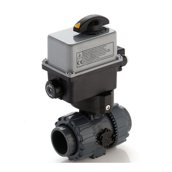
Electrically actuated two-way dual block regulating ball valve
Hide thumbs
1
2
3
4
5
6
7
8
9
10
11
12
13
14
15
16
17
18
19
20
21
22
23
24
25
26
27
28
29
30
31
32
33
34
35
page
of
35
Go
/
35
Bookmarks
Advertisement
Quick Links
Download this manual
VKR/CE DN 10÷50
PVC-U/PP-H/PVDF
ELECTRICALLY ACTUATED TWO-WAY DUAL BLOCK
®
REGULATING BALL VALVE
Table of
Contents
Previous
Page
Next
Page
1
2
3
4
5
Advertisement
Need help?
Do you have a question about the PP-H and is the answer not in the manual?
Ask a question
Questions and answers
Related Manuals for Aliaxis PP-H
Control Unit Aliaxis PVC-U Manual
Electrically actuated two-way dual block regulating ball valve (35 pages)
Control Unit Aliaxis PVDF Manual
Electrically actuated two-way dual block regulating ball valve (35 pages)
Control Unit Aliaxis FIP VKD Manual
Dual block 2-way ball valve (13 pages)
Control Unit Aliaxis VEE Series Manual
(25 pages)
Control Unit Aliaxis Friatec Frialen DAV RED SNAP Assembly Instruction Manual
Pressure tapping valves (28 pages)
Control Unit Aliaxis FIP PVDF Manual
(144 pages)
Control Unit Aliaxis FIP Dual Block VKDIC Quick Start Manual
2-way ball valve (14 pages)
Summarization of Contents
VKR/CE DN 10÷50
Technical Specifications - VKR
Technical Specifications - Electric Actuator
Technical Data
Pressure Variation According to Temperature
Charts showing pressure limits of valve bodies at different temperatures.
Performance Graphs
Pressure Drop Graph
Visual representation of pressure loss across the valve at various flow rates.
Relative Flow Coefficient
Flow rate relative to valve opening percentage.
K100 Flow Coefficient
Q flow generating a specific pressure drop at 20°C.
Electric Actuator Data
Functional Characteristics
Key performance and operational features of the electric actuator.
Power Connection Diagram
Wiring diagram for connecting electrical power to the actuator.
Auxiliary Limit Switch Connection Diagram
Wiring diagram for connecting limit switches for actuator control.
Signal Connections
Dimensions - VKR/CE DN 10÷50 PVC-U
Brackets and Supports
Components Exploded View
Disassembly and Assembly
Disassembly
Step-by-step guide for taking the valve apart.
Assembly
Step-by-step guide for putting the valve back together.
Installation
Print
Rename the bookmark
Delete bookmark?
Delete from my manuals?
Login
Sign In
OR
Sign in with Facebook
Sign in with Google
Upload manual
Upload from disk
Upload from URL
Need help?
Do you have a question about the PP-H and is the answer not in the manual?
Questions and answers