Table of Contents
Advertisement
SERVICE MANUAL
Ver. 1.2 2016.07
• All of the units included in
the HT-NT5 (SA-NT5/SA-
WNT5/Remote control) are
required to confi rming op-
eration of SA-NT5. Check in
advance that you have all of
the units.
Note:
Be sure to keep your PC used for service and
checking of this unit always updated with the
latest version of your anti-virus software.
In case a virus affected unit was found during
service, contact your Service Headquarters.
COMPONENT MODEL NAME
Bar Speaker (Active Speaker System)
Subwoofer (Active Subwoofer)
• Please refer to service manual separately issued for Subwoofer.
Amplifier section
(US)
POWER OUTPUT AND TOTAL HARMONIC
DISTORTION:
(FTC)
Front L + Front R:
With 8ohms loads, both channels
driven, from 200 - 7,000Hz; rated
25W per channel minimum RMS
power, with no more than 1% total
harmonic distortion from 250mW to
rated output.
POWER OUTPUT (reference)
Front L/Front R speaker blocks: 75W
(per channel at 8ohms, 1kHz)
Front tweeter L/Front tweeter R
speaker blocks: 35 W (per channel at
4ohms, 10kHz)
Top tweeter L/Top tweeter R speaker
blocks: 25 W (per channel at 4ohms,
20kHz)
(CH)
POWER OUTPUT (rated)
Front L/R speakers: 36 W (per channel at 8
ohms, 1 kHz)
Front tweeter L/Front tweeter R speaker:
17 W (per channel at 4 ohms, 10 kHz)
Top tweeter L/Top tweeter R speaker:
17 W (per channel at 4 ohms, 20 kHz)
(BR)
The following values were measured at
127 V AC 60 Hz
RMS POWER OUTPUT:
Front L + Front R: 72 W (36 W per
channel × 2, at 8 ohms,
1 kHz, 10% THD*)
Front tweeter L/Front tweeter R
speaker blocks: 34 W (17 W per
channel × 2, at 4 ohms, 10 kHz,
10% THD*)
Top tweeter L/Top tweeter R speaker
blocks: 34 W (17 W per channel × 2,
at 4 ohms, 20 kHz, 10% THD*)
* Total harmonic distortion
(Except US, CH, BR)
POWER OUTPUT (rated)
Front L + Front R: 50W + 50W
(at 8ohms, 1kHz, 1% THD)
POWER OUTPUT (reference)
Front L/Front R speaker blocks: 75W
(per channel at 8ohms, 1kHz)
Front tweeter L/Front tweeter R
speaker blocks: 35 W (per channel at
4ohms, 10kHz)
Top tweeter L/Top tweeter R speaker
blocks: 25 W (per channel at 4ohms,
20kHz)
Inputs
HDMI IN 1/2/3*
ANALOG IN
TV IN (OPTICAL)
Outputs
HDMI OUT (TV (ARC))*
*HDMI IN 1/2/3 and HDMI OUT (TV (ARC))
jacks support HDCP 2.2 protocol. HDCP
2.2 is newly enhanced copyright
protection technology that is used to
protect content such as 4K movies.
9-896-276-03
Sony Video & Sound Products Inc.
2016G33-1
©
2016.07
Published by Sony Techno Create Corporation
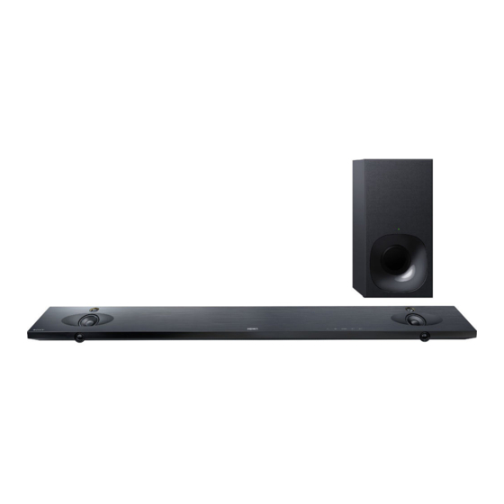
Photo: SA-NT5
HT-NT5
SA-NT5
SA-WNT5
SPECIFICATIONS
2)
HDMI Section
BLUETOOTH standard profiles indicate
Connector
the purpose of BLUETOOTH
Type A (19pin)
communication between devices.
3)
Codec: Audio signal compression and
USB section
conversion format
(USB) port:
4)
Abbreviation for Subband Codec
Type A (For connecting USB memory,
5)
Abbreviation for Advanced Audio
memory card reader, digital still
Coding
camera)
Front L/Front R speaker block section
LAN section
Speaker system
LAN(100) terminal
2-way 3 speaker system, Acoustic
100BASE-TX Terminal
suspension
Speaker
Wireless LAN section
Woofer: 60mm (2 3/8 in.) cone type
Communication system
Tweeter: 14mm (9/16 in.) soft dome
IEEE 802.11 a/b/g/n
type × 2
Frequency band (Except CH)
2.4 GHz, 5 GHz
General
Frequency band (CH)
Power requirements
2.4 GHz - 2.4835 GHz
120 V AC, 60 Hz (US, CND)
5.15 GHz - 5.35 GHz
120 V AC, 50 Hz/60 Hz (TW)
5.725 GHz - 5.85 GHz
120 V - 240 V AC, 50 Hz/60 Hz (EA, BR, LA)
BLUETOOTH section
220 V - 240 V AC, 50 Hz/60 Hz (AEP, RU,
Communication system
UK, AUS, CH, SP, AR)
BLUETOOTH Specification version 4.1
Power consumption
Output
On: 50W
BLUETOOTH Specification Power
Standby mode: 0.5W or less
Class1
[Quick Start/Network Standby] is set to
Maximum communication range
[Off] (default setting): 3 W
1)
Line of sight approx. 30m
[Quick Start/Network Standby] is set to
Maximum number of devices to be
[On] (all wired network ports
registered
connected, all wireless network ports
9 devices
activated): 7W
Frequency band
2)
Dimensions* (approx.) (w/h/d)
2.4 GHz band (2.4GHz - 2.4835GHz)
1,080mm × 58mm × 127mm (42 5/8 in
Modulation method
× 2 3/8 in × 5 in) (without grille frame,
FHSS (Freq Hopping Spread Spectrum)
without wall mounting brackets)
Compatible BLUETOOTH profiles
1,080mm × 64mm × 127mm (42 5/8
A2DP 1.2 (Advanced Audio Distribution
in × 2 5/8 in × 5 in) (with grille frame,
Profile)
without wall mounting brackets)
AVRCP 1.5 (Audio Video Remote
1,080mm × 135mm × 80mm (42 5/8
Control Profile)
in × 5 3/8 in × 3 1/4 in) (without grille
3)
frame, with wall mounting brackets)
Supported Codecs
SBC
4)
, AAC
5)
, LDAC
1,080mm × 135mm × 80mm (42 5/8
in × 5 3/8 in × 3 1/4 in) (with grille
Transmission range (A2DP)
frame, with wall mounting brackets)
20 Hz - 40,000 Hz (LDAC sampling
1)
frequency 96kHz with 990 kbps
*Not including projection portion
transmission)
Mass (approx.)
20 Hz - 20,000 Hz (Sampling frequency
3.2kg (7 lb 7/8 oz) (without grille
44.1kHz)
frame)
The actual range will vary depending on
factors such as obstacles between
devices, magnetic fields around a
microwave oven, static electricity,
cordless phone use, reception
sensitivity, the operating system,
software applications, etc.
HT-NT5
Canadian Model
AEP Model
Australian Model
Chinese Model
Compatible iPod/iPhone models
The compatible iPod/iPhone models are as
follows. Update your iPod/iPhone with the
latest software before using with the
system.
BLUETOOTH technology works with:
iPhone 6s Plus/iPhone 6s/iPhone 6 Plus/
iPhone6/iPhone 5s/iPhone 5c/iPhone 5/
iPhone 4s/iPhone 4
iPod touch (6th generation)/iPod touch
(5th generation)
Wireless transmitter section
Communication system
Wireless Sound Specification version
2.0
Frequency band
2.4GHz (2.4000GHz - 2.4835GHz)
Modulation method
Modulation method
Pi/4 DQPSK
Supplied Accessories
•Bar Speaker (1)
•Grille frame (1)
•Wall mounting brackets (2), Screws (2),
Grille frame support hook (2)
•AC plug adapters (2) (LA)
•Subwoofer (1)
•Remote control (1)
•R03 (size AAA) batteries (2)
•HDMI cable (4K 60p 18Gbps
compatible) (1) (Except AEP, UK)
•Optical digital cable (1) (AEP, UK)
•Startup Guide (1)
•Operating Instructions (1)
Design and specifications are subject to
change without notice.
SOUND BAR
ACTIVE SPEAKER SYSTEM
SA-NT5
US Model
UK Model
E Model
HT-NT5
SA-NT5
Advertisement
Table of Contents

Related Manuals for Sony SA-NT5


Summarization of Contents
Servicing Notes
Unleaded Solder
Information regarding the characteristics and handling of unleaded solder used in circuit boards.
Advance Preparation and Operation Checks
Notes on preparing for operation checks and ensuring all units are available.
Capacitor Electrical Discharge Processing
Procedure for safely discharging capacitors before checking boards to prevent electric shock.
Operation Check Without Heat Sink
Guidelines for performing operation checks with the heat sink removed.
Model Identification
Instructions on identifying the unit model using part and destination codes.
Destination Abbreviations
List of abbreviations used for different model destinations in the service manual.
Notes on Replacing MB-1509 or WLAN/BT Combo Card
Important notes for replacing MB-1509 or WLAN/BT combo cards.
Network Information Writing Method
Procedure for writing network information in service mode after card replacement.
Network and NFC Connection Checking
Methods for checking wireless LAN, wired LAN, and NFC connections.
Notice of MAC Address Change
Information for customers regarding MAC address changes after repair.
Initializing Method
Procedure to return all unit settings to the initial factory state.
Wireless Connection (Link) Work
Procedure for linking the bar speaker and subwoofer after part replacement.
Disassembly
Disassembly Flow
Diagram outlining the step-by-step process for disassembling the unit.
Top Cabinet Block
Procedure for removing the top cabinet assembly, including notes on handling delicate parts.
Touch Board
Steps for accessing and removing the touch board from the unit.
Display Board Block
Procedure for disassembling the display board assembly.
SIRCS Board
Instructions for removing the SIRCS (Remote Control Receiver) board.
Display Board
Detailed steps for removing the display board itself.
Organic EL Indicator Element (OLED1)
Procedure for removing the organic EL indicator element.
Connection Cable with Speaker (Woofer)
Instructions for disconnecting and removing speaker connection cables for the woofer.
Connection Cable with Speaker (Tweeter)
Instructions for disconnecting and removing speaker connection cables for the tweeters.
Loudspeaker (Woofer/Tweeter)
Steps for removing the woofer and tweeter speaker units.
RF Modulator Block
Procedure for accessing and removing the RF modulator block.
RF Modulator (RF1)
Detailed steps for removing the RF modulator (RF1) component.
NFC Board
Instructions for removing the NFC board.
BTW (WIFI) Board
Procedure for accessing and removing the BTW (WIFI) board.
WLAN/BT Combo Card (WIFI1)-1
Part 1 of the procedure for removing the WLAN/BT combo card.
WLAN/BT Combo Card (WIFI1)-2
Part 2 of the procedure for removing the WLAN/BT combo card.
Insulator (Top)
Steps for removing the top insulator component.
Power Cord (AC1)
Procedure for removing the power cord assembly.
Power Board
Instructions for removing the main power board.
AMP Board
Steps for removing the amplifier (AMP) board.
USB-CHUKEI Board
Procedure for removing the USB-CHUKEI board.
BTW (BT) Board
Instructions for removing the BTW (BT) board.
REPEATER Board
Procedure for removing the repeater board.
MB-1509 Board-1
Part 1 of the procedure for removing the MB-1509 board.
MB-1509 Board-2
Part 2 of the procedure for removing the MB-1509 board.
Bottom Chassis Block
Steps for removing the bottom chassis block.
MB-1509 Board Service Position
Illustrates the correct positioning of the MB-1509 board during service.
Power Board Service Position
Illustrates the correct positioning of the Power board during service.
Test Mode
Cold Reset Procedure
Steps to initialize IFCon settings to factory defaults.
All Reset Procedure
Steps to initialize all IFCon and SYSCON settings to factory defaults.
Panel Test
Checks the status of the OLED display, LEDs, buttons, and model information.
Touch-Sensor Debug
Inspects the sensitivity of the touch keys on the unit.
AMP Test
Performs AMP setting and measurement functions.
Acceleration Sensor Test
Measures the unit's installation state (Base or Wall) using the acceleration sensor.
Wireless Sound Cold Reset
Initializes backup information for the subwoofer.
Service Mode
Service Mode Setup
Instructions on how to enter the service mode using a TV monitor and remote.
Main Functions Overview
Lists the main functions available within the service mode.
Service Mode Menu Navigation
Details on navigating the top menu of the service mode.
Diag (Device Test)
Performs tests on individual devices mounted on the board.
Diag (Wireless LAN Test)
Tests wireless LAN and Miracast functionality.
Diag (Bluetooth Device Test)
Performs various tests on the Bluetooth device.
Log Functions (Error Log)
Displays and allows output of error logs.
Factory Initialize
Resets unit settings to factory defaults.
System Information Display
Shows system information such as software and drive details.
EMC Test Mode
Not used for servicing.
Troubleshooting
Power Does Not Turn On
Diagnostic steps for when the unit fails to power on.
Sound Output Issues
Troubleshooting steps for problems related to sound output.
HDMI Video Issues
Diagnostic steps for when HDMI video display is abnormal.
Diagrams
Block Diagram - HDMI Section
Schematic showing the HDMI signal path and related components.
Block Diagram - Main Section
Overall block diagram of the main unit's internal sections.
Block Diagram - AMP Section
Block diagram illustrating the audio amplifier section.
Block Diagram - Panel/Power Supply Section
Block diagram of the unit's panel and power supply circuitry.
Printed Wiring Board - MB-1509 Board
Layout of the MB-1509 board's components and circuitry.
Printed Wiring Board - USB-CHUKEI Board
Component layout for the USB-CHUKEI board.
Schematic Diagram - USB-CHUKEI Board
Circuit diagram for the USB-CHUKEI board.
Printed Wiring Board - AMP Board (Side A) (Suffix-11)
Component layout for the AMP board, side A, Suffix-11 version.
Printed Wiring Board - AMP Board (Side B) (Suffix-11)
Component layout for the AMP board, side B, Suffix-11 version.
Printed Wiring Board - AMP Board (Side A) (Suffix-12)
Component layout for the AMP board, side A, Suffix-12 version.
Printed Wiring Board - AMP Board (Side B) (Suffix-12)
Component layout for the AMP board, side B, Suffix-12 version.
Schematic Diagram - AMP Board (1/2)
Circuit diagram for the AMP board, part 1 of 2.
Schematic Diagram - AMP Board (2/2)
Circuit diagram for the AMP board, part 2 of 2.
Printed Wiring Boards - Antenna Section
Component layouts for antenna boards.
Schematic Diagram - Antenna Section
Circuit diagrams for antenna connections.
Printed Wiring Board - Touch Board
Component layout for the touch board.
Schematic Diagram - Touch Board
Circuit diagram for the touch board.
Printed Wiring Boards - Display/IR Section
Component layouts for display and IR sections.
Schematic Diagram - Display/IR Section
Circuit diagrams for display and IR sections.
Printed Wiring Board - Power Board
Component layout for the power board.
Schematic Diagram - Power Board
Circuit diagram for the power board.
IC Block Diagrams
Block diagrams illustrating the internal structure of key ICs.
IC Pin Function Description
Detailed pin functions for various ICs used in the unit.
Exploded Views
Overall Section
Exploded view showing the main assembly of the unit.
Top Cabinet Section
Exploded view detailing components of the top cabinet.
Bottom Cabinet Section
Exploded view detailing components of the bottom cabinet.
Chassis Section
Exploded view illustrating the chassis and its associated parts.
Main Board Section
Exploded view showing the main board and related components.
Need help?
Do you have a question about the SA-NT5 and is the answer not in the manual?
Questions and answers