Table of Contents
Advertisement
INSTRUCTION MANUAL
HITACHI ROTARY SCREW COMPRESSOR
Air-Cooled Type,
Model : OSP-22S5AI
OSP-22S6AI
OSP-22M5AI
OSP-22M6AI
OSP-37S5AI
OSP-37S6AI
OSP-37M5AI
OSP-37M6AI
[Without a built-in air dryer]
This manual expresses the matters that need your attention as below.
●
Do not fail to observe "WARNING" and "CAUTION," as they assume considerable
●
importance to safety.
WARNING
CAUTION
IMPORTANT
What Marks Say:
: This is a warning. This assumes possible
death or severe injury to the operator if
handled wrongly.
: This is a caution. This assumes possible
injury to the operator and physical
damage, if handled wrongly.
: This means the things that need attention
other than WARNING and CAUTION.
2000 Series
OSP-22S5ARI
OSP-22S6ARI
OSP-22M5ARI
OSP-22M6ARI
OSP-37S5ARI
OSP-37S6ARI
OSP-37M5ARI
OSP-37M6ARI
[With a built-in air dryer]
Before you start operating, be
sure to read this manual carefully
in order to operate the machine
safely and properly.
Also, prepare the manual near
the machine to make it available
at anytime, and refer to it as the
need arises.
: This means prohibition.
MEMO
: This means convenient information
to know.
: This shows reference page number.
: This shows the information specific to
the models with a built-in air dryer.
Advertisement
Table of Contents

Related Manuals for Hitachi HISCREW OSP-37S5AI


Summarization of Contents
2. PARTS DESCRIPTION AND THEIR FUNCTIONS
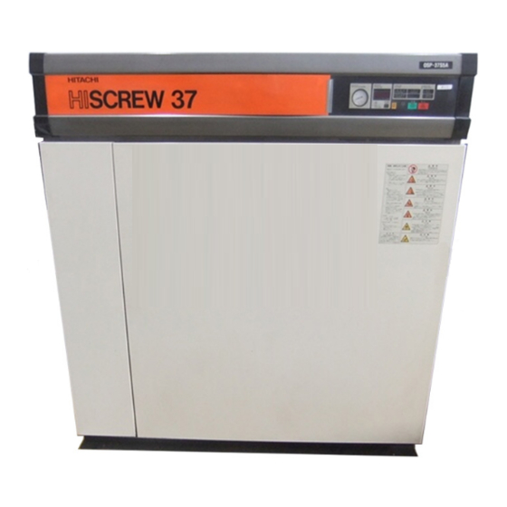
2.1 Appearance
Describes the external view and components of the compressor.
2.2 Main Component Units and their Functions
Details the primary internal components and their roles.
3. HOW TO OPERATE
3.1 Air Compressor Instrumentation
Explains the control panel buttons, lights, and gauges.
3.2 How to Use the Digital Monitor and its Controls
Guides users on operating and interpreting the digital display.
3.3 Initial Start-Up
Provides step-by-step instructions for the first-time operation.
3.4 Setting of the Control Functions
Details how to configure various operational control settings.
3.4.1 Setting of Capacity Control Mode
Explains the settings for different capacity control modes.
3.4.2 How to Set Capacity Control Type to U
Specific steps to set the capacity control type to U.
3.4.3 Enabling the Remote Operation
Describes the methods to enable remote operation of the compressor.
3.4.4 Setting of Air Dryer
Details the settings and operation modes for the built-in air dryer.
4. DAILY CHECK
4.1 Daily Operation Management
Covers recording daily operational status in the logbook.
4.2 Control of Condensate
Explains how condensate is managed and potential issues.
4.3 Lubricant Management
Details lubricant checks, replenishment, and management.
5. TROUBLESHOOTING
5.1 When ALARM or SHUTDOWN is Displayed
Describes how to interpret and respond to alarm/shutdown indicators.
5.1.4 Automatic Restart after Power Supply Interruption (Equipped to M-Type)
Explains the automatic restart function after power interruptions.
5.2 Override Operation
Explains how to perform an override operation for troubleshooting.
5.2.1 Enabling Override Operation
Describes the steps to enable the override operation mode.
5.2.2 When Override Operation is not Allowed
Lists error codes that prevent the override operation.
5.3 SHUTDOWN/ALARM Indications on the Instrument Panel
Lists specific shutdown/alarm codes and their causes/actions.
Dryer Troubleshooting after the DRYER Light Flashes
Guides troubleshooting for issues indicated by the dryer light.
5.4 A List of SHUTDOWNS Not Displayed on Instrument Panel
Identifies shutdown issues not directly indicated on the panel.
6. SYSTEM OF EACH COMPONENT
6.1 Compressed Air/Lubricant System
Illustrates the flow of compressed air and lubricant within the system.
6.2. Capacity Control System
Explains how the compressor capacity is regulated.
6.2.1 Types of Capacity Control
Details the different types of capacity control available.
6.2.2 I-Type Capacity Control
Describes the operation of the I-Type capacity control.
6.2.3 P-Type Capacity Control
Describes the operation of the P-Type capacity control.
6.2.4 Condensate Control Function
Explains the function that minimizes condensate production.
6.2.5 ECOMODE Function
Details how to enable and use the ECOMODE function for energy saving.
6.2.6 Alternative Cutoff/Cutin Pressure Function
Describes an optional feature for adjusting cutoff and cutin pressures.
6.3 Dryer System
6.3.1 Compressed Air Flow
Explains the path of compressed air through the dryer.
6.3.2 Refrigerant Flow
Details the flow and cycle of the refrigerant in the dryer.
7. INSTRUCTIONS FOR INSTALLATION
7.1 Verification of Components
Lists components to check upon receiving the unit.
7.2 Instructions When Conveying
Provides guidance on safely moving and transporting the compressor.
7.3 Instructions When Installing
Covers essential steps and precautions for unit installation.
7.4 Instructions When Piping
Details requirements for connecting air and drain pipes.
7.5 Compressor Room Ventilation
Specifies requirements for compressor room ventilation and air flow.
7.6 Instructions on Electrical Wiring
Guides on proper electrical connections, power supply, and grounding.
7.6.3 Connecting the POWER
Step-by-step guide for connecting the main power supply.
7.6.4 Connecting a ground cable
Instructions for properly grounding the compressor unit.
7.6.5 In case of Remote Operation
Details how to set up and manage remote operation.
7.6.7 Standard voltage wiring diagram (200/220 V)
Provides the electrical wiring diagram for 200/220V models.
8. PERIODIC MAINTENANCE
8.1 Periodic Maintenance for Compressor
Outlines the general schedule for compressor maintenance.
8.2 Maintenance Standards (A)
Specifies maintenance tasks for annual run hours less than 6,000.
8.3 Maintenance Standards (B)
Specifies maintenance tasks for annual run hours less than 3,000.
8.4 Auto Drain Trap for Dryer
Explains cleaning and maintenance procedures for the auto drain trap.
8.5 Performance Check of Relief Valve
Details how to perform a performance check on the relief valve.
8.6 Performance Check of Capacity Control System
Guides on checking the functionality of the capacity control system.
8.7 Replacement of Oil Filter Element
Provides instructions for replacing the oil filter element.
8.8 Cleaning and Replacement of Air Intake Filter Element
Covers cleaning and replacing the air intake filter element.
8.9 Cleaning of Cooler
Explains how to clean the cooler fins to maintain efficiency.
8.10 Inspection and Replacement of Minimum Pressure / Check Valve
Details inspection, adjustment, and replacement of the minimum pressure valve.
8.11 Replacement of Oil Separator Element
Provides instructions for removing and attaching the oil separator element.
8.12 Inspection of Belt
Outlines procedures for checking belt tension and condition.
Need help?
Do you have a question about the HISCREW OSP-37S5AI and is the answer not in the manual?
Questions and answers