Table of Contents
Advertisement
Instructions for the Digitrip RMS 310 3-Pole and 4-Pole Trip Unit Installation
and Operation with L-Frame and MDL-Frame Series C Circuit Breakers
Table of Contents
Description
1
..............................................................
1.1
..................................................
2.0
.............................................................
3.0
3.1
3.2
3.3
..................................................................
.............................................................
3.4
3.5
4.0
..................................................................
4.1
.........................................................
4.2
4.3
4.4
.................................................
5.0
..................................................................
General
5.1
5.2
5.3
5.4
5.5
5.6
...................................................................
6.0
6.1
6.2
..........................................................
7.0
..........................................................
8.0
8.1
...................................................
8.2
A
DEATH, SEVERE PERSONAL INJURY, OR
SUBSTANTIAL PROPERTY DAMAGE CAN RESULT
FROM CONTACT WITH ENERGIZED EQUIPMENT. DO
NOT ATTEMPT INSTALL OR PERFORM
MAINTENANCE ON EQUIPMENT WHILE IT IS
ENERGIZED. ALWAYS VERIFY THAT NO VOLTAGE IS
Effective March 2003 Supersedes I.L. 29C615D dated July 1998
Courtesy of NationalSwitchgear.com
...............................................
.....................................
.....................................
..........................
...........
............................................
..............................
.........................................
.................................
.....................................
................................
.................................
...................................
.........................................
...............................................
.......................................
.......................................
............................................
WARNING
PRESENT BEFORE PROCEEDING WITHTHETASK,
AND ALWAYS FOLLOW GENERALLY ACCEPTED
Page
SAFETY PROCEDURES.
1
CUTLER-HAMMER IS NOT LIABLE FORTHE
1
2
MISAPPLICATION OR MISINSTALLATION OF ITS
2
PRODUCTS.
2
The user is cautioned to observe all recommendations,
2
warnings, and cautions relating to the safety of personnel
3
and equipment as well as all general and local health and
3
safety laws, codes, and procedures.
3
The recommendations and information contained herein
.....
5
are based on Cutler-Hammer experience and judgement,
6
but should not be considered to be all-inclusive or cover-
6
ing every application or circumstance which may arise. If
7
any questions arise, contact Cutler-Hammer for further
7
information or instructions.
7
7
7
7
7
7
7
7
8
8
8
....
8
8
9
9
12
12
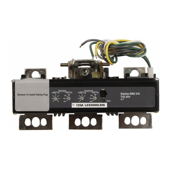
Fig. 1
Digitrip RMS 310 Trip Unit for 3-Pole L-Frame &
MDL Frame Series C Circuit Breaker
12
12
1 .O GENERAL INFORMATION
1.1 Protection
The Digitrip RMS 31 0, illustrated in Figure 1, is an elec-
tronic trip unit that incorporates a microprocessor-based
custom application specific integrated circuit design for
use with Series C L-Frame and MDL Frame Molded Case
Circuit Breakers.
The Digitrip RMS 310 provides true RMS current sensing
for proper correlation with thermal characteristics of
conductors and equipment. Interchangeable rating plugs
I.L. 29C615E
Advertisement
Table of Contents

Related Manuals for Eaton MES3800LS


Summarization of Contents
General Information
Protection Overview
Explains the Digitrip RMS 310 as an electronic trip unit with microprocessor-based design.
Installation
Installation Preparation
Covers inspection, installing the trip unit and rating plug, and checking suitability.
4-Pole Trip Unit Installation
Details removing screws, positioning the trip unit and sensor, and connecting the secondary winding.
Ground Fault Trip Unit Installation
Discusses connecting the neutral current sensor and alarm relay wires, and mounting the trip unit.
3-Pole Trip Unit Installation
Covers removing screws, positioning the trip unit, and tightening retaining screws.
Final Installation Instructions
Includes installing accessories, barriers, and circuit breaker covers.
Principle of Operation
Principle of Operation - General
Describes how the trip unit uses microcomputer functions for tripping based on current and time settings.
Overload Trip Function
Explains trip response to overload currents and the "thermal memory" effect.
Short Delay/Instantaneous Trip
Details trip behavior for short circuit conditions with delay or instantaneous response.
Ground Fault Protection
Covers selective ground fault coordination using pick-up and time delay settings.
Protection Settings
Protection Settings - General
Emphasizes setting protection parameters per engineer specifications and using rotary switches.
Short Delay Pick-up Setting
Describes the seven available settings for short delay pick-up as multiples of the rated current.
Short Delay Time Settings
Explains I²t ramp or flat response time delays available for short delay settings.
Instantaneous Pickup Setting
Details how instantaneous pickup is achieved by setting short delay time to "I".
Ground Fault Pick-Up Setting
Covers the five available settings for ground fault pick-up in multiples of the rated current.
Ground Fault Time Settings
Explains the four available flat response time delay settings for ground fault protection.
Testing
Functional Field Testing
Describes using the STK2 Test Kit via a built-in receptacle for testing trip functions.
Performance Testing for Ground Fault Trip Units
Details requirements and instructions for performance testing of ground fault trip units.
References
Series C L-Frame Circuit Breakers
Lists instruction leaflets and characteristic curves for L-Frame circuit breakers.
Internal Accessories
Lists available internal accessories and their corresponding instruction leaflet numbers.
Need help?
Do you have a question about the MES3800LS and is the answer not in the manual?
Questions and answers