Table of Contents
Advertisement
Advertisement
Table of Contents

Related Manuals for ABB REG670 B30


Summarization of Contents
3. Available functions
Main protection functions
Details on the primary protection functions available in the IED.
Back-up protection functions
Current protection
Functions for overcurrent protection based on phase and residual currents.
Voltage protection
Functions for undervoltage and overvoltage protection.
Frequency protection
Multipurpose protection
General purpose protection functions for current and voltage.
General calculation
Functions for general calculations like filtering.
Control and monitoring functions
Control
Functions for controlling apparatuses and bay operations.
Secondary system supervision
Logic
Logic functions for controlling and interlocking operations.
Communication
Station communication
Protocols and interfaces for substation communication.
Access points
Redundant communication
Details on PRP and HSR redundant communication protocols.
Routes
Specifies paths for data travel between devices in subnetworks.
Basic IED functions
Time synchronization
Functions for time synchronization within the IED.
4. Differential protection
Generator differential protection GENPDIF
Protection for generator phase-to-phase short circuits.
Transformer differential protection T2WPDIF/T3WPDIF
Protection for transformer windings with internal CT ratio matching.
5. Impedance protection
Full-scheme distance measuring, Mho characteristic ZMHPDIS
Up to four zone distance protection for backup detection of short circuits.
6. Wide area measurement system
Synchrophasor report, 16 phasors
Supports IEEE synchrophasor standards for measurements and data communication.
7. Current protection
Instantaneous phase overcurrent protection PHPIOC
High-set short-circuit protection with low overreach and short tripping time.
Directional phase overcurrent protection, four steps OC4PTOC
Directional overcurrent protection with four steps and inverse/definite time delay.
Instantaneous residual overcurrent protection EFPIOC
Instantaneous protection for earth faults with low overreach.
Directional residual overcurrent protection, four steps EF4PTOC
Main protection for phase-to-earth faults and system back-up.
Four step directional negative phase sequence overcurrent protection NS4PTOC
Protection for unsymmetrical faults like phase-phase and phase-earth faults.
8. Voltage protection
Two-step undervoltage protection UV2PTUV
Detects undervoltages for system restoration or back-up protection.
Two step overvoltage protection OV2PTOV
Detects overvoltages during abnormal conditions.
Residual overvoltage protection, two steps ROV2PTOV
Detects residual voltages that may occur during earth faults.
Overexcitation protection OEXPVPH
Protects against generator or transformer overexcitation.
9. Frequency protection
Underfrequency protection SAPTUF
Detects underfrequency for load shedding and remedial action schemes.
Overfrequency protection SAPTOF
Detects overfrequency for generation shedding and load restoring.
Rate-of-change of frequency protection SAPFRC
Early indication of system disturbances and remedial action.
Frequency time accumulation protection FTAQFVR
Protects turbine against abnormal frequency operations.
10. Multipurpose protection
General current and voltage protection CVGAPC
Recommended backup protection with flexible measurement and setting.
11. General calculation
Multipurpose filter SMAIHPAC
Extracts any frequency component from the input signal.
12. Secondary system supervision
Current circuit supervision CCSSPVC
Detects faults in current transformer circuits.
13. Control
Synchrocheck, energizing check, and synchronizing SESRSYN
Provides controlled closing of circuit breakers for asynchronous networks.
14. Logic
Tripping logic common 3-phase output SMPPTRC
Basic function for protection tripping and general start indication.
General start matrix block SMAGAPC
Merges start and directional output signals for trip logic.
Trip matrix logic TMAGAPC
Routes trip signals and other logical outputs to different contacts.
Basic configurable logic blocks
Blocks for adapting configuration to specific application needs.
15. Monitoring
Measurements CVMMXN, CMMXU, VNMMXU, VMMXU, CMSQI, VMSQI
On-line information display for IED service values.
Supervision of mA input signals
Measures and processes signals from measuring transducers.
Disturbance report DRPRDRE
Acquires sampled data for disturbance analysis.
16. Metering
Pulse-counter logic PCFCNT
Counts external binary pulses for energy consumption calculation.
Function for energy calculation and demand handling ETPMMTR
Calculates active and reactive energy and demand.
17. Human machine interface
Local HMI
Interface for setting, monitoring, and controlling the IED.
18. Basic IED functions
Time synchronization
Selects a common source of absolute time for IED synchronization.
19. Ethernet
Access points
Ethernet communication interface for single or redundant station communication.
20. Station communication
Communication protocols
Details on various communication protocols supported by the IED.
21. Remote communication
Analog and binary signal transfer to remote end
Exchanges analog and binary signals between two IEDs.
Line data communication module, short, medium and long range LDCM
Module for communication over distances using optical or electrical interfaces.
22. Hardware description
Hardware modules
Description of various hardware modules within the IED.
Numeric processing module NUM
CPU module handling protection functions and logic.
Power supply module PSM
Provides internal voltages and isolation for the IED.
Binary input module BIM
Module with 16 optically isolated inputs for logical signals.
Binary output module BOM
Module with 24 independent output relays for trip or signaling.
Serial and LON communication module (SLM) for SPA/IEC 60870-5-103, LON and DNP 3.0
Module for SPA, IEC 60870-5-103, DNP3, and LON communication.
Injection equipment hardware
Injection unit REX060
Unit for injecting voltage and current signals into generator/motor circuits.
Coupling capacitor unit REX061
Unit for isolation in rotor injection circuits.
25. Technical data
General
General technical data, definitions, and presumptions.
Energizing quantities, rated values and limits
Specifications for analog inputs and transformers.
Hardware
IED
Details on the Intelligent Electronic Device (IED) hardware.
Electrical safety
Information on electrical safety classifications and standards.
Connection system
Details on CT, VT, power supply, and I/O connectors.
Injection equipment hardware
Injection unit REX060
Unit for injecting voltage and current signals into generator circuits.
Basic IED functions
GPS time synchronization module (GTM)
Module for GPS time synchronization.
26. Ordering for customized IED
Guidelines
Rules for problem-free order management.
28. Ordering for Accessories
Accessories
Details on ordering accessories like antennas, cables, and converters.
GPS antenna and mounting details
Information on GPS antennas and mounting kits.
Interface converter (for remote end data communication)
Converters for C37.94 to G703 and G703.E1.
Test switch
Information on test switches for IED testing.
Protection cover
Covers for protecting rear terminals and components.
Injection equipment
Casing
Description of casing options for injection equipment.
Injection modules
Details on Stator (SIM) and Rotor (RIM) injection modules.
Coupling capacitor unit, REX061
Unit for isolation in rotor injection circuits.
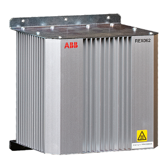
Shunt resistor unit, REX062
Unit required when injection is done via a Signal Injection Transformer.
Combiflex
Key switch for settings
Switch for lock-out of settings via LHMI.
Mounting kit
Kits for side-by-side mounting.
Injection unit for Rotor earth fault protection (RXTTE 4)
Unit for injecting voltage into the rotor circuit.
Configuration and monitoring tools
Tools for connecting LHMI and PC, and LED labels.
Manuals
Documentation included with the IED.
Reference information
Related documents
List of related documents and their numbers.
Need help?
Do you have a question about the REG670 B30 and is the answer not in the manual?
Questions and answers