
Related Manuals for Vertiv Liebert CRV CRD100-0D00A


Summarization of Contents
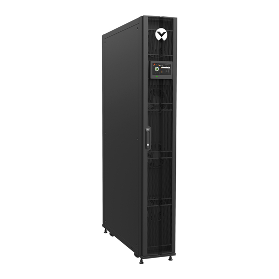
Liebert CRV Row Based Cooling
CRD10 User Manual
User manual for the Liebert CRD10 row based cooling unit.
Important Safety Instructions
Electrical Safety Warnings
Hazards from arc flash, electric shock, and improper wiring.
Mechanical Safety Warnings
Risks from falling units, rotating fan blades, and improper handling.
Environmental and System Safety
Concerns regarding noise levels, refrigerant pressure, and power connections.
Chapter 1: Product Overview
Product Introduction
Overview of the Liebert CRD10 air conditioner and its purpose.
Product Description
Detailed description of the CRD10 cooling unit's system functions.
Model Nomenclature
Explanation of the 12-digit model designation for CRD10 units.
Basic Performance Parameters
Key performance specifications for CRD10 models.
Sound Parameters
Sound level data for the Liebert CRD10 unit across frequency bands.
Main Components of Indoor Unit
Details on primary components within the CRD10 indoor unit.
DC Brushless Compressor
Features and description of the DC Brushless Compressor.
Fan
Information on the energy-efficient EC Fan used in CRD10 models.
Evaporator
Description of the evaporator's design and function.
Electronic Expansion Valve (EEV)
Functionality and design of the EEV for precise refrigerant control.
Electric Heater
Details on the PTC heater used for reheat functions.
Sight Glass
Purpose of the sight glass for observing refrigerant state.
Filter Drier
Role of the filter drier in the refrigeration lifecycle.
Micro-Controller
Features of the micro-controller for unit operation and monitoring.
Unity Card
Functionality of the Unity card for system monitoring and communication.
Condensate Pump
Details on the condensate pump used for drainage.
Liquid Line Solenoid Kit
Function of the solenoid kit to prevent liquid refrigerant issues.
Ramp
Procedure for using the ramp for unit unloading.
Technical Specification
Detailed mechanical and electrical specifications of the unit.
Chapter 2: Installation
Pre-Installation
Preliminary steps for preparing the air conditioner for installation.
Installation Tools
Lists standard tools and utilities required for installation and maintenance.
Prerequisite Arrangements
Requirements for site preparation and necessary materials.
Transportation & Movement
Guidelines and warnings for safely moving and transporting the unit.
Unpacking
Step-by-step instructions for safely unpacking the unit.
Installation Preparation (Site Preparation)
Preparing the installation site, including room and space requirements.
Equipment Room Requirement
Specifies conditions for the equipment room for optimal operation.
Installation Space Requirements
Details required space around the unit for installation and servicing.
Operating and Storage Environment Conditions
Defines conditions for operating and storing the unit.
Operating Condition
Specifies ambient temperature, protection level, and voltage ranges.
Storage Condition
Defines requirements for storing the unit to maintain its condition.
Weight Bearing Capacity
Importance of considering floor load capacity for unit installation.
Refrigerant Charging Requirement
Critical requirement for charging the system with the correct refrigerant.
Inspection
Final checks to ensure all parts are intact and correctly fitted.
Chapter 3: Mechanical Installation
Installation Notes
Important considerations before starting mechanical installation.
System Arrangement during Installation
General layout and arrangement of the CRD10 AC unit.
Product Dimensions
Dimensions and weight of the indoor unit.
Base Plate Pipe Outlet Location & Dimensions
Locations and dimensions for pipe connections on the unit base plate.
Top plate pipe outlet Locations & Dimensions
Locations and dimensions for pipe connections on the unit top plate.
Front Air outlet Locations and Dimensions
Location and dimensions of the unit's front air outlets.
Top frame and front frame
Procedures for installing optional top and front frames.
Top frame installation without front frame
Steps for installing the top frame when the front frame is not used.
Top frame installation with front frame
Steps for installing the top frame along with the front frame.
System Installation Layout
Diagrams illustrating different installation modes for the CRD10 unit.
Installation Procedures
Step-by-step guide for installing the unit.
Leveling the Cabinet
Instructions for leveling the unit cabinet for stability and performance.
Removing the Feet and Fixing the Cabinet
Procedures for removing feet and securing the cabinet.
Cabinet Connection
Steps for connecting adjacent cabinets using provided connectors.
Piping Connections
Guidelines and considerations for connecting refrigerant and drainage pipes.
Removing Filters
Procedure for removing filters before pipe connections.
Connecting the Condensate Drainage Pipe
Instructions for connecting the indoor unit's condensate drainage pipe.
Connecting the Copper Pipes
Procedures for connecting indoor and outdoor unit copper pipes.
Installing Liquid Line Solenoid Valve Kit and Low Ambient Kit
Installation of kits to prevent refrigerant issues and operate in low ambient temps.
Installing Solenoid valve Kit
Steps for installing the solenoid valve kit in the liquid line.
Installing Low Ambient Kit
Instructions for installing the Low Ambient Kit.
Recommended Refrigerant and Oil Charging Amount
Guidelines for charging the system with appropriate refrigerant and oil.
Adjusting the Supply Air Baffle and Sealing the Holes
Instructions for adjusting air baffles and sealing cabinet holes.
Adjusting the supply air baffle
How to adjust the supply air baffle for desired airflow direction.
Sealing the Holes of the Top Plate
Sealing top plate holes to prevent water ingress.
Checklist for Completed Mechanical Installation
Checklist to verify successful mechanical installation.
Chapter 4: Electrical Installation
Installation Notes
Key notes for electrical installation compliance and safety.
CRD10 Wiring Connections
Overview of wiring connections for CRD10 unit components.
Power Cable and Control Cabinet of the Indoor unit
Details on connecting power and control cables to the indoor unit.
Electrical Port location of the indoor unit
Locating electrical ports and components within the indoor unit.
Connecting the Power Cable of the Indoor unit
Steps for connecting the indoor unit's power cable.
Connecting the Power Cable of the outdoor unit
Guidance for connecting power to the outdoor unit.
Connection of the Control Cables
Procedures for connecting various control cables.
Water-Under-Floor Sensor
Instructions for connecting the water-under-floor sensor.
Solenoid Valve Kit
Connection details for the solenoid valve kit.
Transformer connection cable
Information on transformer wiring for voltage compatibility.
Low Ambient Kit
Connection of the Low Ambient Kit power supply.
Rack Sensor
Procedure for connecting rack temperature sensors.
Remote Shutdown
Connecting terminals for remote shutdown functionality.
External Common Alarm
Connecting terminals for external common alarms.
Teamwork Control
Setup and connection for unit teamwork control.
Checklist for the Completed Electrical Installation
Checklist to confirm all electrical installation steps are completed.
Chapter 5: Commissioning Overview
Self Check
Verifying installation meets standards for normal operation and service life.
Preparations for Start-up
Basic checks before the unit can be started up.
Inspection of Pipes
Checks related to pipe installation, solenoid valve, and oil trap.
Vacuuming
Procedure for pulling and verifying deep vacuum on the system.
Inspection of auxiliary parts and cables
Checks on drainage, electrical circuits, and main power supply voltage.
Start-up Inspection
Final inspections before starting the unit, checking fans, heating, and condensers.
Refrigerant Charge
Procedure for charging the air-cooled unit with the correct refrigerant quantity.
Start-up Procedure
Step-by-step guide for the initial start-up of the air conditioner.
First Start-up (or after long standstill)
Steps for first start-up or after extended periods of inactivity.
Automatic Restart
Configuration for automatic unit restart after power interruptions.
Chapter 6: Micro-Controller
Features
Key features of the micro-controller for unit monitoring and operation.
Appearance
Visual appearance of the 7-inch HMI display color screen.
Control Screen
Overview of the main control screen interface and its functions.
Main Screen
Description of the main interface after unit startup.
Main Interface Control Mode
Details on temperature and humidity control modes displayed on the interface.
Password Interface
Interface for accessing menu functions using password levels.
Menu Structure
Hierarchical structure of the micro-controller's menu system.
Run Information
Viewing real-time operational data like temperature, humidity, and status.
Temperature Humidity
Displays real-time temperature/humidity parameters of the device.
Switch Information
View current input and output states of the device's digital signals.
Power Information
Displays unit voltage and frequency information.
Teamwork Information
Displays the status of group information for teamwork control.
Alarm Information
Accessing and viewing current and historical alarm records.
Alarm Status
Monitoring the current alarm status and information of the AC unit.
Alarm History
Viewing historical alarm records, including serial number and type.
Temp/Hum Setting
Interface for setting temperature and humidity values.
Temp Setting
Setting return air, remote, and supply air temperatures.
Hum Setting
Setting the humidity control value.
Parameter Setting
Setting various parameters like teamwork, alarms, communication, and time.
Teamwork Setting
Configuring teamwork parameters such as mode, address, and rotation.
Alarm Setpoint
Adjusting alarm setpoints for temperature and humidity thresholds.
Alarm Attribute
Enabling or disabling specific alarm attributes.
Communication Setting
Configuring communication parameters like protocol and baud rate.
Time Setting
Setting the date and time for the unit.
Display Setting
Configuring display language and address.
Password Setting
Setting or changing user passwords for menu access.
Graph
Querying curves for temperature and humidity over 0-48 hours.
About
Viewing software and service information, including version numbers.
Chapter 7: Maintenance & Troubleshooting
Routine Maintenance & Inspection (Monthly)
Monthly checklist for ensuring proper functionality and checking wear of components.
Routine Maintenance and Inspection (Semi- annually)
Semi-annual checklist for smooth operation and component wear inspection.
Self-Diagnosing Functions
Utilizing built-in diagnostic functions for components and functionality.
Maintenance of Electrical Control Utilities
Processes for maintaining electrical parts and control systems.
Maintenance of Electric Parts
Visual checks and handling for electrical connections and components.
Maintenance of Control System
Checks and tests for control parts, boards, and connections.
Water-Leak-Detector
Recommended location and usage of the water leak detector.
Air Filter Maintenance
Procedures for maintaining the air filter, including cleaning and replacement.
Fan Kit Maintenance
Regular checking of EC fans, including motor status and impeller.
Electrical Heater Maintenance
Periodic monitoring and replacement procedures for the electrical heater.
Condensate pump maintenance
Maintenance procedures for the condensate pump.
Pump Replacement
Steps for replacing the condensate pump.
Pump Maintenance
Cleaning and checking the condensate pump and its float mechanism.
Refrigerating System Maintenance
Basic instructions for maintaining the refrigerating system functionality.
Drainage System Maintenance
Periodic inspection of the water tray for normal drainage operation.
Dismantling the Unit
Procedures for dismantling the unit at the end of its useful life.
Troubleshooting
Guidance for troubleshooting common issues with the unit.
Troubleshooting of the Heating System
Diagnosing and resolving issues related to the heating system.
Troubleshooting of Compressor and Cooling System
Diagnosing and resolving compressor and cooling system problems.
Chapter 8: Regulation (EU) no. 517/2014 (F-gas)
Introduction
Overview of regulations for stationary air conditioners using fluorinated greenhouse gases.
Normative References
List of relevant regulations and standards for F-gas compliance.
Fluorinated Greenhouse Gases
Notes on fluorinated greenhouse gases and their global warming potential.
Operators
Definition and obligations of operators handling F-gas equipment.
Definitions
Definitions related to operators and F-gas regulations.
Obligations
Operator responsibilities for preventing leaks and ensuring checks.
Leakage Detection
Approved methods for checking refrigeration circuits for leaks.
Labelling
Requirements for unit labeling regarding refrigerant quantity.
Record Keeping
Operator requirements for establishing and maintaining leak check records.
Need help?
Do you have a question about the Liebert CRV CRD100-0D00A and is the answer not in the manual?
Questions and answers