Table of Contents
Advertisement
800D SERIES MIXER AMPLIFIER
Note on Firmware Upgrade
Before using the device, upgrade the firmware.
The latest firmware can be downloaded from the product page of the A-812D, A-824D, A-848D on
the TOA Corporation website.
Thank you for purchasing TOA's 800D Series Mixer Amplifier.
Please carefully follow the instructions in this manual to ensure long, trouble-free use of your equipment.
OPERATING INSTRUCTIONS
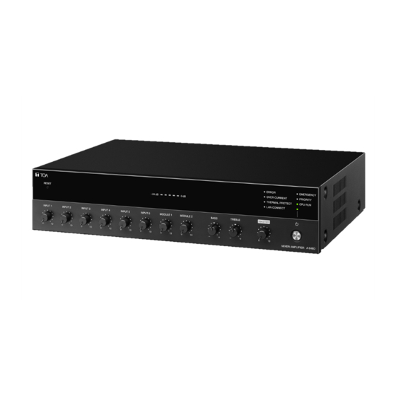
A-812D, A-824D, A-848D
The figure represents the A-812D.
Advertisement
Table of Contents

Related Manuals for Toa A-848D


Summarization of Contents
Nomenclature and Functions (Front Panel)
Power Switch and Indicator
Operation and status indication for the unit's power switch.
Reset Key and Level Meter
Function of the reset key and the LED level meter for output monitoring.
Status Indicators
Explanation of error, protection, network, and broadcast status indicators.
Input Volume Controls
Adjusts the volume level for each of the six input channels.
Nomenclature and Functions (Rear Panel Controls)
Module and Tone Controls
Volume controls for module inputs, and bass/treble tone adjustments.
Master Volume, AC Inlet, and DIP Switches
Master volume adjustment, AC power connection, and DIP switch settings.
Nomenclature and Functions (Rear Panel Terminals 1)
Remote Control Terminals
Terminals for remote master volume, power control, and emergency control outputs.
Chime, Ducker, and Input Settings
Controls for chime volume, ducker depth, and input settings for channels 3/4 and 1/2.
Nomenclature and Functions (Rear Panel Terminals 2)
Speaker and Network Connections
Speaker output terminals, impedance setting, and network terminal connection.
Audio Outputs and Inputs
Recording, pre-amp outputs, and input terminals/settings for channels 5 and 6.
Connections
Speaker Connection
Details on connecting speakers to the unit for low and high impedance outputs.
Input Terminal Connections
Connecting various input signals (microphone, line, modules) to the unit.
Input Signal Settings
Configuration of input sensitivity, phantom power, and routing for inputs 1-6.
Remote Master Volume Control Connection
Connecting a volume controller for remote master volume adjustment.
Power Remote Control Output Connection
Using the output terminal for remote power control of other equipment.
Emergency Control Output Connection
Using the output terminal for remote control during emergency broadcasts.
Control Input Terminal Connection
Connecting contact signals to control priority broadcast functions.
External Equipment Connection (Pre-Amp to Power Amp)
Connecting signal processors between pre-amplifier and power amplifier outputs.
Removable Terminal Plug Connection
Steps for wiring and inserting removable terminal plugs.
Settings
Chime Tone Setting
Setting the desired chime tone using DIP switches 1 and 2.
Module Input Routing
Configuring module inputs for AUDIO or DUCK output via DIP switches 3 and 4.
Priority Broadcast Function
Priority Broadcast Overview
Explanation of the priority broadcast function, levels, and indicators.
Priority Broadcast Modes
Details on Standard and Manual modes for priority broadcast operation.
Manual Mode Operation
Using the Manual mode for checking device operation and muting signals.
Emergency Broadcast
Setting the highest priority level for emergency broadcasts.
Normal Broadcast
Description of the unit's state during normal operation without triggers.
Priority/Emergency Broadcasts and Power State
How priority/emergency broadcasts interact with the unit's power on/off status.
Factory Default Settings
Overview of the default configuration for triggers, priority levels, and inputs.
FCC Requirements
Modifications
Guidelines on modifications and their impact on FCC authorization.
Declaration of Conformity
Traceability Information for USA
Contact and manufacturer information for the US market.
Need help?
Do you have a question about the A-848D and is the answer not in the manual?
Questions and answers