Table of Contents

Related Manuals for Kollmorgen P5000


Summary of Contents for Kollmorgen P5000
- Page 1 P50330 (DC) Installation Manual Edition: B - April 2013 Part Number: 903-050330-00 Original Document Keep all manuals as a product component during the life span of the product. Pass all manuals to future users / owners of the product.
- Page 2 Printed in the United States of America This document is the intellectual property of Kollmorgen. All rights reserved. No part of this work may be reproduced in any form (by photocopying, microfilm or any other method) or stored, processed, copied or distributed by electronic means without the written permission of Kollmorgen.
-
Page 3: Table Of Contents
P50330 Installation │Table of Contents P5000 OVERVIEW P5000 D EFINITION UMBER THER YSTEM OMPONENTS AND YSTEM IAGRAM OW TO USE THIS MANUAL ARRANTY INSTALLING THE P5000 ... -
Page 4: P5000 Overview
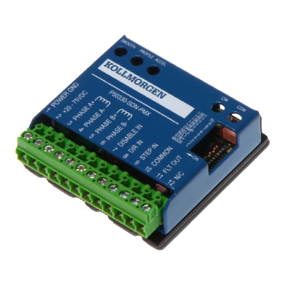
Warranty Information P5000 Definition The P50330-SDN-PMX is a micro-stepping step motor drive with an integral VCO oscillator function. The drive can operate as a conventional step motor drive using its step and direction inputs, or use its internal VCO. Principal features include: •... -
Page 5: Part Number
P50330 Installation │Overview Part Number Other System Components and System Diagram The other components that, along with the drive, comprise a motor control system are: • Indexer or pulse generator • Single power supply (20-75 volts) • Motor Installation guidelines for these components are described in Chapter 2, “Installing the P5000 Stepper Motor Drive.”... -
Page 6: How To Use This Manual
P50330 Installation │Overview The following diagram shows an installation of the drive in a typical system: Figure 1: System Diagram Note: Your installation may vary from this configuration. How to use this manual This manual contains information and procedures to install, setup, and troubleshoot the P5000 stepper motor drive. -
Page 7: Warranty
P50330 Installation │Overview Warranty The Kollmorgen P5000 drives have a one year warranty against defects in material and assembly. Products that have been modified by the customer, physically mishandled, or otherwise abused through mis-wiring or incorrect switch settings are void from the warranty plan. -
Page 8: Installing The P5000
As the user or person applying this unit, you are responsible for determining the suitability of this product for any application you intend. In no event will Kollmorgen be responsible or liable for indirect or consequential damage resulting from the misuse of this product. -
Page 9: Selecting Other System Components
2.3.2 Motor Selection The P5000 is designed for use with Kollmorgen’s POWERMAX II line of hybrid stepper motors or most other 2 phase stepper motors. When using Kollmorgen Motors, the drive’s output waveform is optimized to maximize smoothness in order to achieve the best system performance. -
Page 10: Mounting The P5000
P50330 Installation │Install The choice of power supply voltage depends on the required speed performance of the motor and the motor's inductance. The motor's holding torque and low-speed torque is unaffected by power supply voltage. Supply voltage affects motor power (speed times torque) output and power output increases proportionally with supply voltage. - Page 11 P50330 Installation │ Install the back of the drive. If possible, the drive should be securely fastened to a smooth, flat, non-painted metal surface that will help conduct heat away from the chassis. Never put the drive where it can get wet or where metal or other electrically conductive particles can get on the circuitry.
-
Page 12: Mounting Dimensions
P50330 Installation │Install 2.4.4 Mounting Dimensions Figure 2: Mounting Dimensions 2.4.5 Mounting Guidelines Your installation should meet the following guidelines: • Flat, solid surface capable of supporting the approximate 3.4 oz weight (97 g mass) of the unit • Free of excessive vibration or shock •... -
Page 13: Introduction
P50330 Installation │ Install Wiring is application specific Wiring sizes, wiring practices and grounding/shielding techniques described in the following section represent common wiring practices and should prove satisfactory in the majority of applications. Non-standard applications, local electrical codes, special operating conditions, and system configuration wiring needs take precedence over the information included here. -
Page 14: Power Connection
P50330 Installation │Install Figure 3: Connector Diagram 2.5.2 Power Connection Terminals 1 and 2 connect the P5000 to the DC power supply. Please refer to section 2.3.3 for additional information on power supply considerations. TERM 1: POWER GND. Power supply ground terminal. This is normally wired to the DC power supply '-'. -
Page 15: Motor Connections
P50330 Installation │ Install 2.5.3 Motor Connections Terminals 3, 4, 5, and 6 connect the P5000 to the motor phases. Typically for Kollmorgen Powermax II hybrid stepper motors phases A & /A are black and orange leads; phases B & /B are red and yellow leads. -
Page 16: Command I/O Connections
P50330 Installation │Install Figure 4: Motor Phase Connection Configurations 2.5.4 Command I/O Connections The P5000 has two modes of operation. The drive can operate as a conventional step motor drive using step and direction inputs or it can use its internal Velocity Controlled Oscillator (VCO). -
Page 17: Step Drive Mode (Sw1 On)
P50330 Installation │ Install The connector diagram below shows the input and output functionality for each operation mode: Figure 5: Connector Diagram 2.5.4.1 Step Drive Mode (SW1 ON) The P5000 drive operates as a conventional step motor drive using external single-ended step and direction inputs in this mode. - Page 18 P50330 Installation │Install TERM 8: DIR IN This single-ended input sets motor direction while the STEP IN input is cycled. When +5VDC is applied to the DIR IN input, the motor rotates in the counter-clockwise direction. When 0VDC is applied, the motor rotates in the clockwise direction. DIR IN must be true for 200 nsec before and after the STEP IN pulse edge.
-
Page 19: Vco Mode (Sw1 Off)
P50330 Installation │ Install Step & Dir MODE: 20–75VDC Power applied. Solid Green VCO MODE: 20–75VDC Power applied & zero speed. Flashing Green, VCO MODE only: Motor rotating CW Green, Green, Pause direction. Flashing Red, Red, VCO MODE only: Motor rotating CCW Red, Pause direction. -
Page 20: Configuring The P5000
P50330 Installation │ Configure CONFIGURING THE P5000 This chapter explains how to configure the P5000 after installation. Topics covered are: • Setting up functions using the dip switches (SW1 – SW10) • Setting the five trimpots This section is intended to familiarize the P5000 user with the hardware adjustments and settings required to power and operate the P5000 drive. -
Page 21: Standby Current Reduction
P50330 Installation │ Configure MODE Step Drive Table 2: Operation Mode – SW1 SW1 ON (Default): STEP DRIVE MODE. The P5000 drive operates as a conventional step motor drive using external single-ended step and direction inputs in this mode. The SW1 dip switch must be in the ON position for Step Drive Mode to be active. -
Page 22: Input Pulse Resolution
P50330 Installation │Configure 3.1.3.1 Input Pulse Resolution The input pulse resolution is set by the SEL1 and SEL0 switches (SW3 and SW4) when the P5000 is in Step Drive Mode. SW3 ON and SW4 ON are the default settings. The available input pulse resolutions are full-step, half-step, and 1/10 microstep. -
Page 23: Motor Current
For Kollmorgen POWERMAX II hybrid stepper motors use the Rated Current per Phase from the Kollmorgen Stepper Solutions Catalog to set the drive. When using non-Kollmorgen motors, the motor winding current rating must be compatible with the output current of the drive package. -
Page 24: Trimpot Set Up
P50330 Installation │Configure Table 7: Motor Current Setting – SW6-SW10 Trimpot Set Up Introduction Some of the operational parameters of the P5000 can be set or changed using the five trimpots located on the top of the drive. The trimpots are labeled SMOOTH, PROFILE, ACCEL, CW, CCW. - Page 25 P50330 Installation │ Configure The ACCEL trimpot sets the acceleration and deceleration rates. This trimpot sets the time from zero to full speed. The ramp rate range is 128ms to 32 seconds. Using the example mentioned above, if SW3 and SW4 are in the ON position full speed will be 234 RPM.
-
Page 26: Troubleshooting
P50330 Installation │ Troubleshoot TROUBLESHOOTING This chapter covers troubleshooting of the P5000 drive. Maintaining the P5000 The P5000 drives are designed for minimum maintenance. The following cleaning procedure, performed as needed, will minimize problems due to dust and dirt build-up. Remove superficial dust and dirt from the unit using clean, dry, low-pressure air. -
Page 27: Appendix A: Specifications
P50330 Installation │ Appendices APPENDIX A: SPECIFICATIONS Electrical Input Power Supply 20-75 VDC Rated Drive Output Current (Motor Phase Current) 0 to 2.5 Arms, 3.5 Apeak Motor Inductance Range 1 – 50 mH Step Size 1/10 micro-step. 2000 steps/rev. Signal Input Characteristics Optically isolated. -
Page 28: Mechanical
P50330 Installation │Appendices Mechanical 2.5 x 2.5 x 0.8375 inches (63.5 x 63.5 x 21.3 mm) overall. Dimensions Refer to section 2.4.4. 3.4 oz (97 g) including mating connectors Weight 2 pieces Phoenix Contact p/n 1934900. Mating Connectors PCB terminal block - PT 1.5/ 6-PVH-5.0... - Page 29 About Kollmorgen Kollmorgen is a leading provider of motion systems and components for machine builders. Through world-class knowledge in motion, industry-leading quality and deep expertise in linking and integrating standard and custom products, Kollmorgen delivers breakthrough solutions that are unmatched in performance, reliability and ease-of-use, giving machine builders an irrefutable marketplace advantage.
Need help?
Do you have a question about the P5000 and is the answer not in the manual?
Questions and answers