Table of Contents
Advertisement
Quick Links
UNVENTED (VENT-FREE) INFRARED REMOTE CONTROL
SAFETY INFORMATION AND INSTALLATION MANUAL
WARNING: If the information in this manual is not fol-
lowed exactly, a fire or explosion may result causing
property damage, personal injury or loss of life.
— Do not store or use gasoline or other flammable
vapors and liquids in the vicinity of this or any other
appliance.
— WHAT TO DO IF YOU SMELL GAS
• Do not try to light any appliance.
• Do not touch any electrical switch; do not use any
phone in your building.
• Immediately call your gas supplier from a neighbor's
phone. Follow the gas supplier's instructions.
• If you cannot reach your gas supplier, call the fire
department.
— Installation and service must be performed by a quali-
fied installer, service agency or the gas supplier.
INSTALLER: Leave this manual with the appliance.
CONSUMER: Retain this manual for future reference.
For more information, visit www.desatech.com
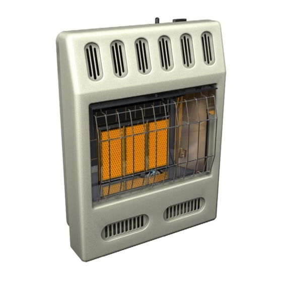
GAS HEATER
MODELS
NZ100, NZ101, NZ102, NZ103
NZ104, NZ105, NZ106, NZ107
NZ116, NZ117, NZ118, NZ119
Actual heater may
vary from illustration.
Advertisement
Table of Contents

Related Manuals for Desa NZ100


Summary of Contents for Desa NZ100
- Page 1 UNVENTED (VENT-FREE) INFRARED REMOTE CONTROL SAFETY INFORMATION AND INSTALLATION MANUAL NZ100, NZ101, NZ102, NZ103 NZ104, NZ105, NZ106, NZ107 NZ116, NZ117, NZ118, NZ119 WARNING: If the information in this manual is not fol- lowed exactly, a fire or explosion may result causing property damage, personal injury or loss of life.
-
Page 2: Table Of Contents
Safety Information ... 2 Local Codes... 4 Unpacking... 4 Product Identification ... 4 Product Features ... 4 Air For Combustion And Ventilation ... 5 Installation ... 7 Operating Heater ... 15 Inspecting Heater ... 20 Cleaning and Maintenance ... 21 Service Hints ... - Page 3 SAFETY INFORMATION Continued Natural and Propane/LP Gas: pane/LP gases are odorless. An odor-making agent is added to these gases. The odor helps you detect a gas leak. However, the odor added to the gas can fade. Gas may be present even though no odor exists. Make certain you read and understand all warnings.
-
Page 4: Local Codes
SAFETY INFORMATION Continued 11. Turn off and unplug heater and let cool before servicing. Only a qualified service person should service and repair heater. 12. Operating heater above elevations of 4,500 feet (1,371 m) could cause pilot outage. 13. To prevent performance problems, do not use propane/LP fuel tank of less than 100 lbs. -
Page 5: Air For Combustion And Ventilation
AIR FOR COMbUSTION AND VENTILATION WARNING: This heater shall not be installed in a confined space or unusually tight con- struction unless provisions are provided for adequate combus- tion and ventilation air. Read the following instructions to insure proper fresh air for this and other fuel-burning appliances in your home. -
Page 6: Determining Fresh-Air Flow For Heater Location
AIR FOR COMbUSTION AND VENTILATION Continued DETERMINING FRESH-AIR FLOW FOR HEATER LOCATION Determining if You Have a Confined or Unconfined Space Use this work sheet to determine if you have a confined or unconfined space. Includes the room in which you will install Space: heater plus any adjoining rooms with doorless passageways or ventilation grills between the... -
Page 7: Installation
AIR FOR COMbUSTION AND VENTILATION Continued vENTILATION AIR Ventilation Air From Inside Building This fresh air would come from an adjoining unconfined space. When ventilating to an adjoining unconfined space, you must provide two permanent openings: one within 12" of the ceiling and one within 12"... -
Page 8: Installation Items
INSTALLATION Continued INSTALLATION ITEMS Before installing heater, make sure you have the items listed below. • for propane/LP gas, external regulator (supplied by installer) • piping (check local codes) • sealant (resistant to propane/LP gas) • equipment shutoff valve * •... - Page 9 INSTALLATION Continued INSTALLING HEATER TO WALL Mounting Bracket Locate mounting bracket in heater carton. Re- move mounting bracket from heater carton. Figure 5 - Mounting Bracket Removing Front Panel Of Heater 1. Remove the four painted screws, two on each side of front panel. 2.
- Page 10 INSTALLATION Continued Attaching To Wall Stud Method For attaching mounting bracket to wall studs 1. Drill holes at marked locations using 9/64" drill bit. 2. Place mounting bracket onto wall. Line up last hole on each end of bracket with holes drilled in wall.
- Page 11 INSTALLATION Continued MOUNTING HEATER TO FLOOR WITH OPTIONAL FLOOR KIT Mounting Base Feet to Heater 1. Lay heater cabinet on its back on a table with the heater bottom overhanging the table edge. 2. Align holes in base foot with mounting holes on bottom of cabinet (see Figure 12).
- Page 12 INSTALLATION Continued CONNECTING TO GAS SUPPLY WARNING: This appliance requires a 3/8" NPT (National Pipe Thread) inlet connection to the pressure regulator. WARNING: A qualified ser- vice person must connect heater to gas supply. Follow all local codes. WARNING: For natural gas, never connect heater to private (non-utility) gas wells.
-
Page 13: Checking Gas Connections
INSTALLATION Continued IMPORTANT: Install an equipment shutoff valve in an accessible location. The equip- ment shutoff valve is for turning on or shutting off the gas to the appliance. Apply pipe joint sealant lightly to male NPT threads. This will prevent excess sealant from going into pipe. - Page 14 INSTALLATION Continued Gas Control Valve Meter Figure 19 - Checking Gas Joints for Natural Gas Gas Control Valve Propane/LP Supply Tank Figure 20 - Checking Gas Joints for Propane/LP Gas PRESSURE TESTING HEATER GAS CONNECTIONS 1. Open equipment shutoff valve (see Figure 18, page 13).
-
Page 15: Operating Heater
OpERATING HEATER FOR YOUR SAFETY READ bEFORE LIGHTING WARNING: If you do not fol- low these instructions exactly, a fire or explosion may result causing property damage, per- sonal injury or loss of life. A. This appliance has a pilot which must be lighted by hand. -
Page 16: Manual Lighting Procedure
OpERATING HEATER Continued WARNING: Always operate manual control heaters at the locked positions. Operation between these positions may create a possible health hazard if used in a poorly ventilated room. Read owner’s manual for complete instructions. CAUTION: Do not try to ad- just heating levels by using the equipment shutoff valve. - Page 17 OpERATING HEATER Continued ROOM Figure 25 - LCD Display buttons MODE - Changes modes from ON, THERMO and OFF. DOWN - Lowers set temperature in THERMO mode. UP - Increases set temperature in THERMO mode TIME/PROGRAM - Activates time setting and ROOM activates PROGRAM mode.
- Page 18 OpERATING HEATER Continued To Activate the Program Mode A short push (press and release) on TIME/ PROGRAM button will activate or deactivate program mode. A long push (press and hold for more than 5 seconds) on TIME/PROGRAM button will enter into setting of program. When the program mode is activated, the P-1 and P-2 icons and the word OFF will display on the screen.
- Page 19 OpERATING HEATER Continued Note: When lock-out mode is activated letters CP will appear in room temp window. After activation is complete room temp window will default back to displaying room temperature. If any buttons are pressed room temp window will then display CP indicating remote control is in lock-out mode.
-
Page 20: Inspecting Heater
OpERATING HEATER Continued OPERATING bLOWER This heater has a thermostatic blower that will automatically turn ON or OFF. Note: Your heater and thermostat blower will not turn on and off at the same time. The heater may run for several minutes before the blower turns on. -
Page 21: Cleaning And Maintenance
If so, contact DESA Heating Products’ Technical Service Department at 1-866-672-6040. When calling please have your model and serial numbers of your heater ready. You can also visit DESA Heating Products’ tech- nical service web site at www.desatech.com. www.desatech.com Pilot Assembly... -
Page 22: Troubleshooting
WARNING: Turn off and unplug heater and let cool before servicing. Only a qualified service person should service and repair heater. CAUTION: Never use a wire, needle or similar object to clean ODS/pilot. This can damage ODS/pilot unit. Note: All troubleshooting items are listed in order of operation. ObSERvED PRObLEM When ignitor button is pressed in, there is no spark... - Page 23 ObSERvED PRObLEM ODS/pilot lights but flame goes out when control knob is released Burner(s) does not light after ODS/pilot is lit Delayed ignition of burner(s) Burner backfiring during combustion 118621-01B TROUbLESHOOTING Continued POSSIbLE CAUSE 1. Control knob not fully pressed in 2.
- Page 24 ObSERvED PRObLEM Burner plaque(s) does not glow Slight smoke or odor during initial operation Heater produces a clicking/ ticking noise just after burner is lit or shut off Remote does not function White powder residue forming within burner box or on adja- cent walls or furniture Heater shuts off in use (ODS operates)
- Page 25 WARNING: If you smell gas • Shut off gas supply. • Do not try to light any appliance. • Do not touch any electrical switch; do not use any phone in your building. • Immediately call your gas supplier from a neighbor’s phone. Fol- low the gas supplier’s instructions.
-
Page 26: Illustrated Parts Breakdown And Parts List
ILLUSTRATED pARTS bREAkDOwN MODELS NZ100, NZ101, NZ102, NZ103, NZ104, NZ105, NZ106, NZ107, NZ116, NZ117, Nz118 AND Nz119 www.desatech.com 118621-01B... -
Page 27: Parts List
This list contains replaceable parts used in your heater. When ordering parts, follow the instructions listed under Replacement Parts on page 30 of this manual. NO. PART NO. DESCRIPTION 097159-04 Piezo Ignitor 107673-01 Front Panel 107676-01 Front Panel 107672-01 Front Panel 107675-01 Front Panel 107673-06PP Front Panel 107676-06PP Front Panel... -
Page 28: Illustrated Parts Breakdown And Parts List
ASSEMbLY This list contains replaceable parts used in your heater. When ordering parts, follow the instructions listed under Replacement Parts on page 30 of this manual. Burner Assembly for Models NZ100, NZ101, NZ104, NZ105, NZ116 and NZ117 NO. PART NO. -
Page 29: Specifications
NZ100, NZ104, NZ116 • Natural Gas • 18,000 Btu/hr • Piezo Ignition • Pressure Regulator Setting: 6" W.C. • Inlet Gas Pressure* (in. of water): Maximum - 10.5", Minimum - 7" • Average Heater Weight: 22 lb (10 kg) • Average Shipping Weight: 25.5 lb (11.6 kg) NZ101, NZ105, NZ117 •... -
Page 30: Replacement Parts
PARTS NOT UNDER WARRANTY Contact authorized dealers of this product. If they can’t supply original replacement part(s), either contact your nearest Parts Central (see page 31) or call DESA Heat- ing Products at 1-866-672-6040 for referral information. When calling DESA Heating Products, have ready •... -
Page 31: Parts Central
These Parts Centrals are privately owned businesses. They have agreed to support our customer’s needs by providing original replacement parts and accessories. Tool & Equipment Co. 5 Manila Ave Hamden, CT 06514-0322 1-800-397-7553 203-248-7553 Portable Heater Parts 342 N. County Rd. 400 East Valparaiso, IN 46383-9704 219-462-7441 1-888-619-7060... -
Page 32: Warranty Information
We make no other warranty, expressed or implied. LIMITED wARRANTIES FOR NEw AND FACTORY DESA Heating Products warrants this heater and any parts thereof, to be free of defects New Products: in materials and workmanship for two (2) years from the date of first purchase, when operated and maintained in accordance with the manufacturer's instructions.
Need help?
Do you have a question about the NZ100 and is the answer not in the manual?
Questions and answers