
Related Manuals for Lenze EMB8252-E


Summarization of Contents
Preface and General Information
About These Operating Instructions
Provides context, terminology, and updates for the operating instructions.
Scope of Delivery
Details the items included in the product package upon purchase.
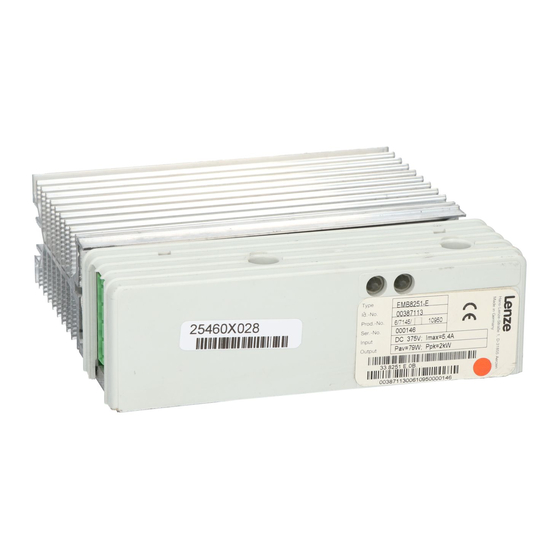
825X Brake Unit Labelling
Explains how Lenze 825X brake units are identified via nameplate markings.
825X Brake Unit Application
Defines the intended use and operational conditions for 825X brake units.
Legal Regulations for Brake Units
Outlines liability and warranty terms associated with the brake units.
Safety Information
Personnel Responsibility for Safety
Defines operator and qualified personnel roles and responsibilities for safe operation.
General Safety Information
Covers general warnings, potential hazards, and safe operating practices.
Safety Information Layout
Explains the meaning of safety icons and signal words used in the manual.
Residual Hazards
Details specific remaining risks and precautions, such as after power disconnection.
Technical Data
Product Features
Lists the key characteristics and types of the 825X brake units.
General Data and Operating Conditions
Specifies environmental limits, vibration resistance, and approvals for the units.
Brake Unit Rated Data
Provides electrical specifications, power ratings, and current limits for brake units.
Brake Resistor Assignment
Table matching motor power to recommended Lenze brake resistors.
Cable Protection and Cross-sections
Recommendations for overcurrent relays and cable cross-sections.
Unit Dimensions
Physical dimensions of the brake units for installation planning.
Installation
Mechanical Installation
Guidelines for physical mounting, space requirements, and ventilation.
Mechanical Installation Notes
Important considerations for mounting, cooling, and vibration resistance.
Fixing Rail Assembly
Instructions for mounting the brake units using a fixing rail.
DIN-Rail Assembly
Instructions for mounting the brake units on a DIN rail.
Electrical Installation Safety
Critical safety procedures for electrical connection and operator protection.
Brake Unit Protection
Measures to protect the brake unit from electrostatic discharge and condensation.
Cable Specifications
Requirements for cable types, PE conductors, and screen quality.
Power Connection Guidelines
Recommendations for cable cross-sections, lengths, and screening for power connection.
Wiring 8251 Module to 820X Controller
Schematic diagram for connecting the 8251 brake module to an 820X controller.
Wiring 8252 Module to 821X Controller
Schematic diagram for connecting the 8252 brake module to an 821X controller.
Wiring 8253 Chopper to 821X Controller
Schematic diagram for connecting the 8253 brake chopper to an 821X controller.
Temperature Monitoring Connection
Instructions for connecting temperature monitoring for safe switch-off.
Supplement
Accessories
Details available accessories, specifically brake resistors with dimensions.
Glossary
Definitions of technical terms used throughout the manual.
Index
Alphabetical listing of topics and their corresponding page numbers for navigation.
Need help?
Do you have a question about the EMB8252-E and is the answer not in the manual?
Questions and answers