Advertisement
Quick Links
1.0 SAFETY INFORMATION
•
The provision of the electrical supply and the connection of the unit to the electrical supply must
be carried out by a qualified electrician.
•
Isolate from power supply before removing any covers. During installation / maintenance ensure
all covers are fitted before switching on the mains supply.
•
All-pole disconnection from the mains as shown in the wiring diagram must be incorporated
within the fixed wiring and shall have a minimum contact separation of 3mm in accordance with
latest edition of the wiring regulations.
•
This unit must be earthed.
•
Ducting must be securely fixed with screws to the spigot to prevent access to live parts. Duct
runs terminating close to the fan must be adequately protected by suitable guards.
•
This appliance should not be used by children or persons with reduced physical, sensory or
mental capabilities or lack of experience and knowledge, unless they have been given supervision
or instruction concerning the safe use of the appliance by a person responsible for their safety.
Children shall not play with the appliance. Cleaning and user maintenance shall not be carried
out by children.
1.1 Symbols
GENERAL WARNING
Signifies a general warning regarding hazard specified by supplementary information.
ELECTRIC SHOCK
This unit must be completely electrically isolated before any panels are removed. Check
mains supply and control connections.
ROTATING PARTS
This unit contains fast moving rotational parts which may start automatically. It is the
sole responsibility of the installer to adequately guard these components.
REFER TO INSTRUCTION MANUAL
Read and understand the installation and maintenance manual before installing,
operating or maintaining this product.
Nuaire |
Western Industrial Estate
ESBH
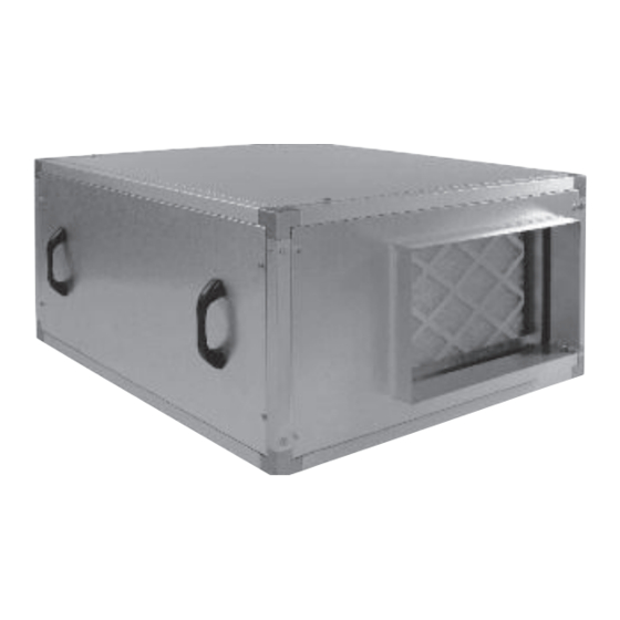
Ecosmart Boxer Air Handling Units
Installation Manual
|
|
| nuaire.co.uk
Caerphilly
CF83 1NA
22. 09. 20. Document Number 671188
EMC Directive
2014/30/EU
LVD Directive
2014/35/EU
1
Advertisement

Related Manuals for NuAire Ecosmart Boxer ESBHS3


Summarization of Contents
1.0 Safety Information
General Warning
Signifies a general warning regarding hazard specified by supplementary information.
Electric Shock
This unit must be completely electrically isolated before any panels are removed.
Rotating Parts
This unit contains fast moving rotational parts which may start automatically.
Refer to Instruction Manual
Read and understand the installation and maintenance manual before installing, operating or maintaining this product.
1.2 Important Information
Read Instructions Thoroughly
Read these instructions completely and thoroughly before working with the product.
Keep Instructions Accessible
Keep these instructions in a location where they are accessible to all users at all times.
Include Operating Instructions
Always include the operating instructions when you pass the product on to third parties.
1.3 Personal Protective Equipment
Protective Steel Toed Shoes
Recommended for handling heavy objects.
Full Finger Gloves
Recommended for handling sheet metal components.
Semi Fingerless Gloves
Recommended for light work requiring tactile dexterity.
Safety Glasses
Recommended for cleaning/cutting operations or exchanging filters.
Reusable Half Mask Respirators
Recommended for replacing filters which have been in contact with normal room or environmental air.
2.0 Introduction
Standard System Components
Lists components typically incorporated in a standard ESBH system.
Optional Extras
Lists optional components that may be included in the system.
2.1 Code Description
Range
Specifies the product range as Ecosmart Boxer AHU.
Airflow Type
Indicates if the unit is for Extract (EX) or Supply (S) airflow.
Unit Size
Defines the available sizes for the unit, ranging from 1 to 7.
Heating Type
Specifies the heating type, either Electric (E) or LPHW (L).
Cooling Type
Specifies the cooling type, either CHW (C) or DX (D).
2.2 Typical Unit Arrangements
Non-Modular Unit Arrangement (Sizes 1 and 2)
Illustrates typical arrangements for non-modular ESBH units of sizes 1 and 2.
Modular Unit Arrangements (Sizes 3 - 7)
Shows typical arrangements for modular ESBH units of sizes 3 to 7.
2.3 Dimensions & Weights
Availability of Details
Full details are available from the Nuaire Technical Estimating Department.
2.4 Handling
Inspection Upon Receipt
Inspect equipment upon receipt and before lifting to ensure safety checks are complete.
Lifting Procedures
Use appropriate lifting gear like forklifts or cranes, with spreaders for slings.
Weight Information
Note the weight of the unit from the rating plate.
Handling Multi-Module Sections
Handle each section individually; do not stack for lifting or storage.
3.0 Mechanical Installation
Competent Person Requirement
Installation must be completed by competent persons in accordance with industry practice and regulations.
3.1 Joining Modules
Single Section Units (Sizes 1 & 2)
Units 1 and 2 are single section and require no assembly.
Multi-Section Units (Sizes 3-7)
Units 3-7 are multi-section, requiring bolting of flanges and use of fish-plates for base frames.
Inter-connecting Looms
Ensure all inter-connecting wiring looms are connected between adjoining modules.
Unit Position Selection
Select position ensuring adequate access for services, commissioning, inspection, and maintenance.
3.3 Installation Location
Indoor Installation
Install indoors away from heat sources, steam, or water spray on a secure, level surface.
Outdoor Installation
Install outdoors on a secure, level surface using the base frame and weather roof.
3.4 Heating & Cooling Pipe Connections
Flow Valve Setting
The flow valve is not factory set and requires adjustment by the commissioning engineer.
Pipe Connection Sizes
Details pipe connection sizes (BSP) for Frost, CHW, and LPHW coils across unit models.
4.0 Electrical Installation
Competent Person & Isolation
Electrical wiring must be by a competent person with local isolation means.
Ecosmart Control Notes
Notes on 'burst fire' control, voltage drops, soft starting, and pre-set inverters.
Model Type Connection
Pay attention to the model type on the rating plate for correct connection.
4.1 Electrical Information
Unit Model Electrical Data
Provides FLC (Fan Only) and Electric Heater (Max Power) data for various unit models.
4.2 Wiring Diagrams
Wiring Diagram ESBHS(1-2), ESBHEX(1-2)
Shows the wiring diagram for ESBHS(1-2) and ESBHEX(1-2) models.
Wiring Diagram ESBHS(1-2)-L, ESBHS(1-2)-LD
Detailed wiring diagram for ESBHS(1-2)-L and ESBHS(1-2)-LD models.
Wiring Diagram ESBHS(1-2)-E
Detailed wiring diagram for ESBHS(1-2)-E models.
Electric Heater Control Adjustment
Do not set temperature above 30°C for electric heater control.
Wiring Diagram ESBHEX(3-7)
Wiring diagram for ESBHEX(3-7) models, showing connections for Ecosmart control.
Wiring Diagram ESBHS(3-7)-E
Wiring diagram for ESBHS(3-7)-E models, detailing connections for Ecosmart and heater controls.
Adjacent Module Connections
Notes on connecting additional controls and sensors from adjacent modules to Ecosmart.
Wiring Diagram ESBHS(3-7)-L, ESBHS(3-7)-LD
Wiring diagram for ESBHS(3-7)-L and ESBHS(3-7)-LD models, including actuator and sensor connections.
Wiring Diagram ESBHS(3-7)-LC
Wiring diagram for ESBHS(3-7)-LC models, detailing connections for LPHW and CW coil actuators.
4.3 Connections
Mains Connections
Guidelines for sizing and terminating mains cables for units and modular sections.
Control Connections
Details on 'Net' connectors for sensors, manual controls, and fan linking.
Ecosmart 'Net' Connections
Shows the plug-in connectors for Ecosmart 'Net' connections.
Switched Live (SL) Terminal
Information on using the Switched Live terminal to activate the fan.
Damper Connections
Details on connecting dampers for open/close signals and return signals.
Damper Connections Drive Open / Spring Close
Wiring for dampers with Drive Open / Spring Close operation.
Damper Connections Drive Open / Drive Close
Wiring for dampers with Drive Open / Drive Close operation.
Volt Free Relay Contacts
Information on volt-free contacts, their ratings, and usage for fan run/fault signals.
Volt Free Connections
Diagram showing volt-free connections for run and fault signals.
Data Cable Installation
Guidelines for installing SELV data cables, including separation and maximum run length.
Maximum Number of Devices
Specifies the maximum number of devices that can be connected via the data cable.
Other Low Voltage Cables
Guidance for low voltage cable runs, keeping them short and within limits.
4.3.9 BMS Input Signals
BMS Connection
How to connect the BMS signal via a plug-in connector.
BMS Connections
Diagram showing BMS connection points.
BMS Signal Response Table
Table showing system response to 0-10V DC BMS signals for different ventilation modes.
5.0 Commissioning
5.1 Electrical Commissioning
Steps for electrical commissioning of the unit.
Commissioning PCB
Diagram of the commissioning PCB with LED indicators.
Test Button Operation
How to use the test button to check fan operation.
LED Indication
Explanation of the status indicated by the PWR, STANDBY, FAN 1, FAN 2, HEATING, COOLING, FAULT, FROST, Tx, Rx LEDs.
Maximum Airflow Rate Adjustment
Procedure for measuring and adjusting the maximum airflow rate.
Maximum/Trickle Airflow Rate Adjustment
Procedure for measuring and adjusting the trickle airflow rate.
4.3.10 LPHW Actuator Connections
LPHW Actuator Connection
How to connect LPHW actuators to control and LPHW modules.
Actuator Wiring Change
Wiring changes depend on the direction of operation of the actuator.
LPHW Actuator Connections
Diagram showing LPHW actuator wiring configurations.
5.2 Mechanical
Wet Systems Flow Valve Setting
Setting the flow valve for wet systems as per general commissioning procedures.
Frost Protection
Importance of frost protection for coils and pipework, recommending antifreeze solution.
DX Coils
Notes on DX coils, condenser units, and installer responsibility for connection and commissioning.
6.0 Maintenance
Maintenance Schedule Adherence
Importance of adhering to the maintenance schedule and referring to previous reports.
Power Isolation for Maintenance
Isolate power supply before removing covers; allow 5 mins for inverter discharge.
6.1 Routine Maintenance
Unit Cleaning and Corrosion Treatment
Clean all areas of the unit and treat any corrosion.
Access Door Checks
Check access doors for leakage, adjust locks, and replace gaskets as needed.
Drain Tray Cleaning
Clean and repair drain trays if necessary.
6.2 Every 3 Months
Filter Checks and Cleaning
Check and clean/change filters every 3 months for optimal performance.
Condensate Drain Cleaning
Ensure condensate drains are cleaned clear for free water flow.
Heat Exchanger Inspection
Inspect fin coil banks and heat exchangers, clean if necessary.
6.3 Annually
Annual Unit Inspection
Thoroughly inspect unit components for corrosion and treat damaged areas.
Electrical Terminal Tightening
Tighten all electrical terminals within the unit annually.
Earth Connection Checks
Check all earth connections annually.
Control Damper Checks
Check control damper blades and operation of actuators and linkages.
Coil Face Inspection
Inspect coil faces and remove any dust.
6.4 Checking Belt Tension
Belt Tension Measurement
Measure span length and apply force to check belt deflection (16mm/metre).
Pinch Bolt Tightening
Tighten the pinch bolts as part of belt tensioning.
6.5 Adjusting Drive Belt Tension (Sizes 3-6)
Drive Belt Tension Adjustment (Sizes 3-6)
Procedure for adjusting drive belt tension for units sizes 3-6.
6.6 Adjusting Drive Belt Tension (Size 7)
Drive Belt Tension Adjustment (Size 7)
Procedure for adjusting drive belt tension for unit size 7.
6.7 Changing a Drive Belt
Drive Belt Replacement
Steps for replacing a drive belt, including motor plate adjustments.
7.0 Warranty
Warranty Period and Coverage
Details the 5-year warranty, covering parts and labour for the first year.
Warranty Void Conditions
Conditions under which the warranty becomes void, such as modification or misuse.
UK Mainland Warranty Application
States warranty applies to UK mainland per Conditions of Sale.
Maintenance and Warranty
Failure to maintain the unit as recommended will invalidate the warranty.
8.0 End-of-Life and Recycling
Recyclable Components
Lists components that can be largely recycled at end-of-life, such as fans, motors, sheet metal, and plastics.
Safe Dismantling Procedures
Ensure product is made safe from supplies before dismantling by qualified personnel.
9.0 After Sales and Replacement Parts
Contacting After Sales Support
Information on how to contact After Sales for technical assistance or spare parts.
Ordering Replacement Parts
Instructions for ordering spares, including quoting serial and part numbers.
Declaration of Incorporation and Information for Safe Installation, Operation and Maintenance
Machinery Designation and Directives
Declares the machinery designation, types, and relevant EC Council Directives.
Applied Standards
Lists the applied harmonised and national standards used for the product.
General Installation Requirements
General safety requirements for system installation, including guarding and electrical compliance.
Information Supplied with Equipment
Details the documentation provided with the equipment, including data sheets and rating plates.
Commissioning Requirements
Lists general pre-commissioning checks for safe operation, including foreign bodies, electrical safety, and fastenings.
Operational Requirements
Requirements for safe operation, including access panels and taking equipment out of service if faulty.
Maintenance Requirements
Notes on maintenance requirements, correct tool usage, and safety during panel removal.
Need help?
Do you have a question about the Ecosmart Boxer ESBHS3 and is the answer not in the manual?
Questions and answers