Advertisement
Table of Contents
1.0 INTRODUCTION
The information contained in this document provides details of
installation, operation and maintenance for installers and users of the
ESBH Ecosmart Boxer range of air handling units.
A standard system incorporates the following, as appropriate to fan
type:
•Inlet section
•Filters
•Electric or LPHW heater
•Chilled Water or DX coil
•Belt or Direct Drive section
•Ecosmart control
•Fan failure circuit
•Integral temperature sensor
Optional extras may include:
•Silencers
•Dampers
•Heat Exchangers
•Inlet and Outlet Terminals
•Weathering Roof
•Sensors
•User controls
For systems which include supply fans with heating and/or cooling
coils, other than where the BMS has control, the appropriate user
control is required.
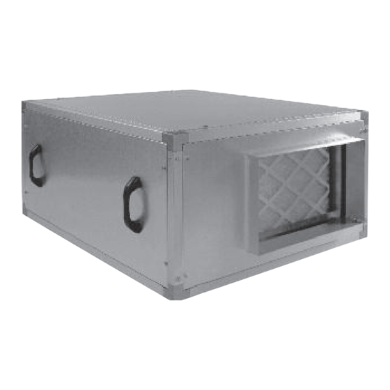
Figure 1. Typical module arrangement.
Electric Heater
nuaire.co.uk
029 2085 8400
ESBH
Ecosmart Boxer Air Handling Units
Installation and Maintenance
Fan Section
Code description: XBOXER XBC Ventilation Unit
ESBH S * - L C
|
| |
| |
1
2 3 4 5
1. Ecosmart Boxer Range (High Efficiency)
2. S = Supply Unit
E = Extract Unit
3. * = Unit Size (1-7)
4. N = No Heater
L = LPHW Coil
E = Electric Heater
5. C = CHW Coil
D = DX Coil
IMPORTANT
UNITS OF MODULAR CONSTRUCTION: Units sizes 3 and
above will be supplied in modular sections, their assembly
and wiring between controls, sensors and actuators located in
each section is the responsibility of the installer and is
discussed within this document.
IMPORTANT
ECOSMART CONTROL BOXES - Units sizes 3 and above,
incorporate control boxes on external casing as shown in
Figure 1.
Cooler
LPHW Heater
13. 03. 19. Document Number 671188
The EMC Directive
2014/30/EU
The Low Voltage
Directive
2014/35/EU
Silencer
1
Advertisement
Table of Contents

Subscribe to Our Youtube Channel
Related Manuals for NuAire ESBH Series


Summary of Contents for NuAire ESBH Series
- Page 1 ECOSMART CONTROL BOXES - Units sizes 3 and above, incorporate control boxes on external casing as shown in Figure 1. Figure 1. Typical module arrangement. Silencer Cooler LPHW Heater Fan Section Electric Heater nuaire.co.uk 029 2085 8400 13. 03. 19. Document Number 671188...
- Page 2 1.2 Dimensions & Weights Full details, with project specific documents and drawings are available from the Nuaire Technical Estimating Department. 2.0 HANDLING Figure 4. Upon receipt of the equipment an inspection should be made, and before commencement of lifting ensure that normal equipment safety checks have been carried out.
-
Page 3: Installation
Where ancillaries such as silencers, bag commissioning engineer. filters, frost heaters etc. are to be fitted, each additional component is supplied with a fixing kit (Figure 6). nuaire.co.uk 029 2085 8400 13. 03. 19. Document Number 671188... -
Page 4: Unit Model
ESBHEX2, ESBHS2-L 7.3A and the unit must be provided with means of local isolation (by ESBHS2-E 7.3A 24kW others) for maintenance purposes. A suitable isolator is available from Nuaire as a separate option. ESBHEX3, ESBHS3-L ESBHS3-E 27kW ESBHEX4, ESBHS4-L ESBHS4-E 36kW... - Page 5 Connections Fault to Damper Frost Trickle Test Heat demand signal Run signal Fault signal NET connections for Earth 400V 50Hz ECOSMART devices 3ph +N mains supply for fan and heater nuaire.co.uk 029 2085 8400 13. 03. 19. Document Number 671188...
- Page 6 Section A is an adjacent module in which additional controls and sensors are installed. Ensure these devices are connected to the Ecosmart control by terminating at points B & C. nuaire.co.uk 029 2085 8400 13. 03. 19. Document Number 671188...
- Page 7 Outlet Inlet sensor sensor Cooling Signal for Connect to inlet Frost Signal for demand DX2 coil sensor after unit alarm DX1 coil signal signal if fitted if fitted is assembled nuaire.co.uk 029 2085 8400 13. 03. 19. Document Number 671188...
- Page 8 Outlet Inlet sensor sensor Cooling Frost Signal for Signal for Connect to inlet demand DX2 coil sensor after unit alarm DX1 coil signal if fitted is assembled signal if fitted nuaire.co.uk 029 2085 8400 13. 03. 19. Document Number 671188...
- Page 9 1 minute before starting. Note: If a damper is not fitted, connect a link wire from OP to RET. This will cancel the delay. nuaire.co.uk 029 2085 8400 13. 03. 19. Document Number 671188...
-
Page 10: Setting To Work
Fan 2 TEST = Test button SL run on Connection, commissioning and setting to work is the Heating responsibility of the condensing unit installer Cooling Fault Frost Trickle Test LED indicators nuaire.co.uk 029 2085 8400 13. 03. 19. Document Number 671188... -
Page 11: Maintenance
If the unit is heavily soiled it may be more convenient to remove from 0.5kg to 0.8kg. the fan / motor assemblies. If Nuaire controls and or remote indicators are fitted, remove the covers and carefully clean out the interiors as •Tighten the pinch bolts. - Page 12 GENERAL In addition to the particular requirements given for the individual product, the following The equipment referred to in this Declaration of Incorporation is supplied by Nuaire to general requirements should be noted. be assembled into a ventilation system which may or may not include additional Where access to any part of equipment which moves, or can become electrically live are components.
Need help?
Do you have a question about the ESBH Series and is the answer not in the manual?
Questions and answers
how can we diagnose faults? please reply
Faults in the NuAire ESBH Series can be diagnosed using the LED indicators:
- A red LED for FAN 1 or FAN 2 indicates a fault in the respective fan.
- The Fault LED illuminates when any fault is present.
- The PWR green LED shows the unit has power and is operating normally.
- The STANDBY LED is on when the fan is not running.
These indicators help identify the presence and location of faults.
This answer is automatically generated
The has shutdown and the fault light is illuminated. What can the fault be for us to investigate further? is there a fault list?
When the fault light is illuminated on the NuAire ESBH Series, possible faults include:
- Fan 1 fault (if FAN 1 LED is red)
- Fan 2 fault (if FAN 2 LED is red)
- General fault present on the unit
The fault light indicates that a fault is present, and the specific issue can be identified by checking the individual fan LEDs.
This answer is automatically generated
sorry this is the correct image of the fault
@Mr. Anderson but why? how can we diagnose the problem?