Table of Contents
Advertisement
I N S TA L L AT I O N , O P E R AT I O N A N D
M A I N T E N A N C E
I N S T R U C T I O N S
Air-Cooled Liquid Chillers
Reversible heat pumps
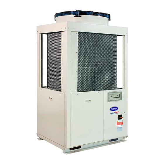
30RB/30RQ 040R-160R
Rated cooling capacity 40-160 kW
R-32
* The availability of sizes and options depends on the country. Please contact your local commercial dealer for more information.
Translation of the original document
Advertisement
Table of Contents

Related Manuals for Carrier Aquasnap 30RQ 160R


Summarization of Contents
2 - RECEIPT OF GOODS
2.1 - Checking the equipment received
Check unit and accessories for damage, missing parts, or incomplete shipment.
3 - HANDLING AND POSITIONING
3.1 - Handling
Carrier recommends specialized company for unloading; keep unit packaged until final placement.
3.2 - Positioning
Install outdoors in a public-inaccessible, protected area, respecting clearances and ensuring level installation.
4 - DIMENSIONS, CLEARANCES, MINIMUM INSTALLATION DISTANCES
4.1 - 30RB/30RQ 040R-080R, units with and without hydraulic module
Diagrams showing dimensions and clearances for 30RB/30RQ 040R-080R units (with/without hydraulic module).
4.2 - 30RB/30RQ 090R-160R, units with and without hydraulic module
Diagrams showing dimensions and clearances for 30RB/30RQ 090R-160R units (with/without hydraulic module).
4.3 - 30RB/30RQ 040R-080R, units with water buffer tank module
Diagrams showing dimensions and clearances for 30RB/30RQ 040R-080R units with water buffer tank module.
4.4 - 30RB/30RQ 090R-160R, units with water buffer tank module
Diagrams showing dimensions and clearances for 30RB/30RQ 090R-160R units with water buffer tank module.
4.5 - Free spaces and Installing several units
Guidelines for free space between multiple units and maximum solid surface height for installation.
4.6 - Positioning of ATEX zones around the unit
Information on ATEX zones around units due to refrigerant type, requiring trained personnel and specific equipment.
5 - PHYSICAL AND ELECTRICAL DATA FOR THE UNITS
5.1 - Physical properties: 30RB/30RQ 40R-160R
Details on physical properties: sound levels, dimensions, weight, compressors, refrigerant, and oil for 30RB/30RQ 40R-160R.
5.2 - Electrical data notes: 30RB/30RQ 040R-160R
Notes and values for electrical data: voltage, input power, current draw, and start-up current for 30RB/30RQ 040R-160R.
5.3 - Short circuit current withstand capability
Short-circuit withstand capability data for TN systems, including rated short-time and peak currents.
5.4 - Electrical data notes for the hydraulic module
Electrical data for hydraulic module pumps and motors: efficiency, power input, and current draw.
5.5 - Electrical data notes for the compressors
Notes on compressor electrical data including nominal current, max current, LRA, and starting current.
5.6 - Distribution of compressors per circuit
Table showing the distribution of compressors (DSF series) across different circuits for various unit models.
5.7 - Comments on electrical data
Notes on electrical data, including power supply, control box contents, field connections, and environmental conditions.
6 - ELECTRICAL CONNECTION
6.1 - Power supply
Power supply requirements: voltage, phase imbalance, and warnings for incorrect supply.
6.2 - Voltage phase imbalance (%)
Explanation and example calculation for determining voltage phase imbalance percentage.
6.3 - Power connection/disconnect switch
Information on the power connection point and earth connection for the unit's disconnect switch.
6.4 - Recommended cable sections
Guidelines for selecting appropriate cable sections based on installation site characteristics and regulations.
6.5 - Power cable access routing
Details on power cable access routing and warnings regarding incorrect supply voltage or phase imbalance.
6.6 - Field-installed control wiring
Important information and precautions for field-installed control wiring, including safety risks and dual electric insulation.
6.7 - Electric and power reserve for the user
Information on the control circuit power reserve available for user applications and connections.
7 - APPLICATION DATA
7.1 - Operating range
Operating ranges for air-cooled and water-cooled exchangers: min/max temperatures and conditions.
7.2 - Minimum heat transfer fluid flow rate (units without factory-fitted hydraulic module)
Minimum flow rate for heat transfer fluid in units without hydraulic module to ensure exchange and prevent fouling.
7.3 - Maximum heat transfer fluid flow rate (units without factory-fitted hydraulic module)
Maximum flow rate for heat transfer fluid in units without hydraulic module, limited by pressure drop and Delta T.
7.4 - Variable flow water type heat exchanger (units without factory-fitted hydraulic module)
Guidelines for using variable flow water heat exchangers, noting flow rate changes and system water volume requirements.
7.5 - System minimum water volume
Formula and factors for determining system minimum water volume required for stable operation.
7.6 - System maximum water volume
Table of maximum loop volumes compatible with expansion vessels for pure water or ethylene glycol.
7.7 - Water type heat exchanger water flow rate
Table showing minimum and maximum water flow rates for the heat exchanger, applicable for pure water.
7.8 - Pressure drop curves for the water exchanger and standard water inlet/outlet piping
Graphical representation of pressure drop curves for water flow rates in the water exchanger.
8 - WATER CONNECTIONS
8.1 - Operating precautions and recommendations
Precautions and recommendations for hydraulic circuit connections, including water analysis, treatment, and material compatibility.
8.2 - Water connections
Schematic diagrams of hydraulic circuits with and without hydraulic modules, detailing components and installation points.
8.3 - Units without hydraulic module
General information on setting nominal flow rate for units without hydraulic module using a manual control valve.
8.4 - Units with hydraulic module and fixed-speed pump (for brine application only)
Reference to 'Units without hydraulic module' chapter for general information on fixed-speed pumps.
8.5 - Units with hydraulic module and variable-speed pump - pressure differential control
Control of variable-speed pumps based on maintaining a constant pressure differential value.
8.6 - Units with hydraulic module and variable-speed pump - temperature difference control
Control of variable-speed pumps based on maintaining a specific temperature difference between water inlet and outlet.
9 - NOMINAL SYSTEM WATER FLOW RATE CONTROL
9.1 - Available static pressure for the installation
Data on available static pressure for units with hydraulic module (fixed/variable speed pumps) at 50 Hz.
10 - SYSTEM START-UP
10.1 - Checks before system start-up
Comprehensive checklist for system verification before start-up, including installation, safety, and refrigerant checks.
10.2 - Commissioning
Guidelines and precautions for unit commissioning, emphasizing supervision by a qualified engineer and pre-start checks.
10.3 - Essential points to check
Key checks for compressors (rotation, temperature, current), hydraulics (flow rate, cleaning), and refrigerant charge (leaks).
11 - MAIN COMPONENTS OF THE UNIT AND OPERATING CHARACTERISTICS
11.1 - Compressors
Description of hermetically sealed scroll compressors, their sub-function components, and safety features.
11.2 - Lubricant
Information on compressor oil charge, oil level check procedure, and important notes on oil type and quantity.
11.3 - Air heat exchanger
Details on the all-aluminium micro-channel coils (MCHE) used in the air heat exchanger.
11.4 - Fans
Description of fan motor assemblies, including impeller material, motor type, insulation, and compliance with eco-design regulations.
11.5 - Electronic expansion valve (EXV)
Description of the EXV, its function, and the sight glass for mechanism movement and liquid gasket checks.
11.6 - Moisture indicator
Purpose of the moisture indicator for checking unit charge, moisture presence, and its color change indication.
11.7 - Filter drier
Role of the filter drier in keeping the circuit clean, its moisture indicator, and signs of a dirty element.
11.8 - Water type heat exchanger
Description of the brazed plate heat exchanger with two refrigerant circuits and its hydraulic connections.
11.9 - Refrigerant
Information on units operating with R32 fluid, ATEX zones, and compliance with applicable recommendations.
11.10 - High-pressure safety pressostat
Details on high-pressure safety pressostats with automatic reset, located at the discharge of each circuit.
11.11 - SmartVuT™ control
Characteristics of the SmartVuT™ control interface, including screen size, user-friendliness, and security features.
12 - OPTIONS
12.1 - Tables of options
Tables listing available options for 30RB/30RQ units, their part numbers, descriptions, and advantages.
12.2 - Description
Detailed descriptions of various options, including hydraulic modules, fan configurations, and control systems.
12.2.4 - Units with fans with available pressure (Option 12)
General information on units with fans and available pressure (Option 12), including installation requirements and duct connection.
12.2.5 - Brine option
Information on evaporator low pressure and frost protection based on antifreeze amount, and recommended procedures.
12.2.6 - Unit operation with a free cooling drycooler
Operating principle of units with free cooling drycooler, optimizing energy savings by using low outdoor air temperatures.
13 - STANDARD MAINTENANCE
13.1 - Level 1 maintenance
Simple maintenance procedures for users, including visual inspections, checks, and cleaning of air-cooled exchangers.
13.2 - Level 2 maintenance
Level 2 maintenance requiring specific expertise, covering electrical, hydraulic, and mechanical checks.
13.3 - Level 3 maintenance
Level 3 maintenance requiring specialized skills, performed only by manufacturer or authorized personnel.
13.4 - Tightening of the electrical connections
Table of torque values for tightening electrical connections of various components like terminals, breakers, and contactors.
13.5 - Tightening torques for the main fastenings
Table of torque values for tightening main fastenings such as compressor brackets, nuts, and screws.
13.6 - Air heat exchanger
Recommendations for inspecting and cleaning air heat exchanger coils, including specific cleaning procedures and warnings.
13.7 - Water type heat exchanger
Checks for the water type heat exchanger, including insulation, heaters, probes, connections, and local regulations.
13.8 - Frequency inverter
Important notes and precautions for working on the variable frequency drive, including isolation and discharge time.
13.9 - Refrigerant volume
Procedure for checking refrigerant charge correctness by monitoring subcooling in cooling mode.
13.10 - Refrigerant properties
Table of saturated temperatures and relative pressures for R32 refrigerant.
14 - FINAL SHUTDOWN
14.1 - Shutting down
Procedure for shutting down the units, including separating from energy sources and draining.
14.2 - Recommendations for disassembly
Information on product disassembly, referencing REACH regulations and using original lifting equipment.
14.3 - Fluids to be recovered for treatment
List of fluids to be recovered for treatment, including refrigerant and heat-transfer fluid.
14.4 - Materials to be recovered for recycling
List of materials to be recovered for recycling, including copper, aluminium, plastics, and insulation.
14.5 - Waste Electrical and Electronic Equipment (WEEE)
Guidelines for disassembling and processing the equipment as Waste Electrical and Electronic Equipment (WEEE).
15 - UNIT START-UP CHECKLIST FOR INSTALLERS PRIOR TO CONTACTING THE MANUFACTURER
Preliminary information
Fields for preliminary information gathering before contacting the manufacturer, including job name, location, and contractor details.
Equipment
Fields for recording equipment details such as model and serial number for compressors and air handling units.
Preliminary equipment check
Checklist for preliminary equipment verification, including shipping damage, level installation, and electrical connections.
Check air handling systems
Checks for air handling units, chilled water valves, fluid piping, air venting, and pump operation.
Unit start-up
Checklist for unit start-up, including pump connection, oil level, leak checks, and voltage imbalance.
Evaporator water loop check
Checks for the evaporator water loop, including volume, corrosion inhibitor, frost protection, and piping.
Checking the pressure drop across the evaporator (without hydraulic module) or ESP(1) (with hydraulic module)
Procedure for checking evaporator pressure drop and determining flow rate using pressure drop curves.
Carry out the QUICK TEST function
Instructions to carry out the QUICK TEST function, including checking user menu configuration and setpoints.
Temperatures and pressures
Recording of operational temperatures and pressures once the machine has stabilized, including evaporator and circuit parameters.
Need help?
Do you have a question about the Aquasnap 30RQ 160R and is the answer not in the manual?
Questions and answers