Table of Contents
Advertisement
Advertisement
Table of Contents

Related Manuals for Panasonic MCDJT3230


Summarization of Contents
Model Designation Codes
Driver Designation Codes
Explains the coding system for driver model designations.
Motor Designation Codes
Explains the coding system for motor model designations.
MINAS-LIQI Capabilities
Quick and Stable Operation
Highlights performance in quick and stable machine operation.
Vibration and Noise Reduction
Details features that minimize vibration and noise.
Accessory Offerings
Lists available serviceable accessories for the system.
General Specifications
Basic Dimensions and Environment
Covers basic physical dimensions and environmental operating conditions.
Position Control Specifications
Details specifications related to position control functionality.
Pulse Input Specifications
Outlines the specifications for pulse input signals.
Appearance and Part Names
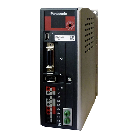
220V Size B Appearance
Physical overview and connection points for 220V Size B units.
220V Size C Appearance
Physical overview and connection points for 220V Size C units.
Connector Configuration
USB and I/O Connector Details
Configuration details for USB (X1) and I/O (X2) connectors.
Multi-function Input/Output Allocation
Mapping functions to multi-function input/output pins.
Input Signal Setup Parameters
Parameter titles for input signal selection and function mapping.
Command Pulse Input Functions
Details on command pulse input signals and their functions.
Common Output Signal Functions
Details on common output signals and their functions.
Multi-function Output Allocation
Mapping of functions to multi-function output pins.
Other Connector Functions
Power supply, ground, and motor connections.
Signal Interface Diagrams
Interface Circuit Schematics
Diagrams showing input/output signal interface circuit configurations.
Specific Connector Details
Encoder Connector (X3)
Encoder connector pin assignments and specifications.
Motor and Power Connector (X4)
Motor and power supply connector details.
Front Panel Operation
Front Panel Configuration
Overview of the front panel components and display.
Rotary Switch (RSW) Control
Operation and settings of the rotary switch for gain control.
Operation Methods
How to operate the front panel and interpret its displays.
Class (0) Parameters
Rotational Direction and Auto-Tuning Setup
Parameters Pr0.00 and Pr0.02 for direction and tuning.
Command Pulse and Electronic Gear Settings
Parameters Pr0.06-Pr0.13 for pulse input and electronic gear.
Deviation and Encoder Settings
Parameters Pr0.14-Pr0.16 for deviation and encoder setup.
Class (1) Parameters
Position and Velocity Loop Gains
Parameters Pr1.00, Pr1.01, Pr1.05, Pr1.06 for loop gains.
Feed Forward and Switching Parameters
Parameters Pr1.11-Pr1.19 for feed forward and switching.
Class (2) Parameters
Adaptive and Notch Filter Settings
Parameters Pr2.00-Pr2.12 for adaptive and notch filters.
Damping Filter Settings
Parameters Pr2.13-Pr2.21 for damping filters.
Command Smoothing and FIR Filters
Parameters Pr2.22-Pr2.23 for command filters.
Class (4) Parameters
Input Selection Parameters
Parameters Pr4.00-Pr4.05 for SI input selection.
Input/Output Function Mapping
Mapping of function numbers to SI and SO signals.
Status and Speed Setting Parameters
Parameters Pr4.31-Pr4.36 for status and speed settings.
Brake and Warning Parameters
Parameters Pr4.37-Pr4.42 for brake and warning settings.
Class (5) Parameters
Electronic Gear Numerator Settings
Parameters Pr5.00-Pr5.02 for electronic gear numerators.
Alarm and Limit Settings
Parameters Pr5.10-Pr5.20 for alarm, limits, and input/output settings.
Torque Limit and Pulse Settings
Parameters Pr5.21-Pr5.33 for torque and pulse settings.
Class (6) Parameters
Deviation, Gain, and Torque Settings
Parameters Pr6.02, Pr6.05-Pr6.09 for deviation, gain, and torque.
Alarm and Time Settings
Parameters Pr6.14, Pr6.15, Pr6.18, Pr6.27 for alarm and time settings.
Tuning and Masking Parameters
Parameters Pr6.31, Pr6.37, Pr6.38 for tuning and masking.
Need help?
Do you have a question about the MCDJT3230 and is the answer not in the manual?
Questions and answers