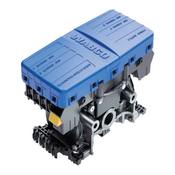
Summarization of Contents
1 General Information
Symbols Used in Documentation
Explanation of symbols used throughout the document for hazard alerts, notes, and references.
Obtaining WABCO Product Information
Guidance on how to find additional maintenance, service, and product information from WABCO resources.
2 Safety Information
Safe Work Environment Provisions
Guidelines for ensuring a safe working environment during vehicle maintenance and service operations.
Understanding Hazard Alert Messages
Explanation of DANGER, WARNING, CAUTION, and NOTICE messages to prevent personal injury or damage.
Trailer Grounding and ESD Protection
Procedures for proper trailer grounding and protection against electrostatic discharge during service tasks.
Vehicle Electrical Grounding Guidelines
Recommendations for ensuring correct common chassis ground points for vehicle electrical system integrity.
3 Introduction
3.1 Identifying iABS
Locating the iABS system identification tag on the Electronic Control Unit (ECU) to identify the system.
iABS Part Numbers
List of part numbers for various WABCO iABS trailer ABS systems, aiding in system identification.
3.2 iABS Trailer ABS Parts
Information on WABCO iABS replacement parts and warranty reference for obtaining copies.
3.3 What is WABCO's iABS Trailer ABS?
Explanation of WABCO's iABS Trailer ABS system, its features like PLC and CAN capabilities.
3.4 System Configuration
Definition of ABS configurations based on the number of sensors and modulator valves used in the system.
3.5 How Trailer ABS Works
Explanation of how the WABCO ABS system monitors and controls wheel speed during braking to prevent lock-up.
3.6 System Components
Overview of the major components of the WABCO iABS Trailer ABS system, including ECU, sensors, and valves.
4 ABS Questions and Answers
4.1 The ECU
Explanation of how the ECU activates, performs self-diagnostics, and responds to wheel lock-up situations.
4.2 Power Line Carrier (PLC)
Details on PLC communications, multiplexing, its implementation in ABS, and how it works.
4.3 ABS Indicator Lamps
Information on the function, operation, and types of ABS indicator lamps on the dash and trailer.
4.4 Types of Faults
Definitions and explanations of existing and intermittent faults within the ABS system and their detection.
4.5 Frequently Asked Questions
Answers to common questions regarding ABS valve crack pressure, trailer bouncing, and brake light illumination.
5 System Configurations
5.1 iABS Installation Diagrams
Illustrations showing sensor and ECU/valve assembly locations for different iABS configurations and mounting orientations.
5.2 Power Cable Wiring Diagrams
Diagrams detailing the power cable connections, pin assignments, and junctions for the iABS system.
6 Diagnostics
6.1 PLC Diagnostics Information
Important information regarding PLC failure diagnostics using blink codes and troubleshooting wiring harness issues.
6.2 TOOLBOX PLUS™ Software
Overview of the PC-based diagnostic program for WABCO products, including its functions and required interfaces.
6.3 Initial Power-up Check
Procedure for checking the initial power-up sequence, self-test clicks, and indicator lamp behavior of the ABS system.
6.4 Power and Ground Checks
Steps for performing power and ground checks on the ABS ECU power connector using voltage and resistance tests.
6.5 Blink Code Diagnostics
Method for obtaining blink codes using Ignition Power Activation to diagnose electrical faults and their corresponding actions.
7 Component Replacement
7.1 Wheel Speed Sensor
Instructions for removing and installing the wheel speed sensor, including testing procedures and gap adjustment.
7.2 ABS Relay Valve
Procedures for removing and installing the standard ABS relay valve, including safety precautions and air system release.
7.3 ECU/Valve Assembly
Guidelines for removing and installing the ECU/Valve Assembly, with specific instructions for mounting types.
8 Sensor Adjustment and Component Testing
8.1 Testing Wheel Speed Sensors
Procedures for testing wheel speed sensor resistance and output voltage, including gap adjustment and troubleshooting no output.
8.2 Checking ABS Functions
Recommendations for testing vehicle ABS after installation and diagnostics, including end of line checks.
8.3 ABS External Modulator Valve
Procedure for measuring resistance across ABS external modulator valve solenoid coils for proper function.
8.4 End of Line Testing
Requirement for end of line testing on iABS installations using TOOLBOX PLUS™ Software for verification.
8.5 End of Line Testing without TOOLBOX PLUS™ Software
Procedure for performing end of line tests without TOOLBOX PLUS™ Software for 2S/1M standard systems, using indicator lamps.
8.6 Inspect Sensor and Air Line Installation
Guidelines for inspecting sensor and air line installation for various ABS configurations, ensuring correct routing and connections.
8.7 Trailer Identification
Information on identifying the trailer and preparing necessary details before contacting WABCO customer support.
9 Troubleshooting
9.1 Automatic Lift Axle Troubleshooting
Troubleshooting steps for the Automatic Lift Axle system, covering function activation, pneumatic, and electrical checks.
9.2 Tag Axle Troubleshooting
Troubleshooting steps for the Tag Axle system, covering function activation, component checks, and system plumbing.
9.3 Axle Load Monitoring Troubleshooting
Troubleshooting for Axle Load Monitoring, including system connection, sensor readings, and calibration issues.
9.4 Tire Inflation Communication System Troubleshooting
Troubleshooting for the Tire Inflation Communication System, focusing on status lamp operation and broadcasting issues.
9.5 Door Ajar System Troubleshooting
Troubleshooting for the Door Ajar System, covering function activation, connection checks, and plumbing.
9.6 Integrated Speed Switch System
Troubleshooting for the Integrated Speed Switch System, including function activation, cable verification, and connection checks.
10 Appendix I
10.1 Trailer ABS Indicator Lamp on Vehicle Dash
Explanation of trailer ABS indicator lamp operation, bulb check, and responses to ECU signals for service technicians.
11 Appendix II
11.1 Installing Sensors on Non-ABS-Prepped Axles
Detailed instructions for applying grease and installing sensors on non-ABS axles, including routing and testing.
12 Appendix III
12.1 Cable Routing Guidelines
Best practices for securing wires and routing cables to prevent damage, vibration, and ensure reliable connections.
12.2 Cable Strain Relief Guidelines
Importance of cable strain relief for system performance and durability, covering excess cable length and connector strain.
13 Appendix IV
13.1 Vehicle Electrical Grounding Guidelines
Ensuring a correct common chassis ground point for vehicle electrical system protection against noise and ensuring proper function.
14 Appendix V
14.1 Parts and Variant List
List of WABCO iABS parts and variant configurations including part numbers, CAN/GIO capability, and control direction.


Need help?
Do you have a question about the iABS 4S/2M Standard and is the answer not in the manual?
Questions and answers