Table of Contents
Advertisement
Quick Links
Advertisement
Table of Contents

Related Manuals for WABCO TP2205


Summary of Contents for WABCO TP2205
- Page 1 TRAILERCAST WITH BATTERY INSTALLATION GUIDE TP2205...
-
Page 3: Table Of Contents
Symbols Used in this Document ........................5 How to Obtain Additional Maintenance, Service and Product Information ............6 How to Obtain Parts and Kits ..........................6 WABCO TOOLBOX PLUS™ Software ......................6 WABCO Academy ..............................6 WABCO Online Product Catalog ........................6 Your Direct Contact to ZF CVS ..........................7 Safety Information ...............................8... - Page 4 Connecting to the Internal Sensors ........................29 12.2 Connecting to the Internal Sensors (SMS) ......................29 12.3 WABCO TPMS Manager ..........................30 12.4 WABCO TPMS Manager Software Update......................31 Assembly of the Internal Sensor SMS ........................33 13.1 Safety Information ............................33 13.2 Preparing the Installation ..........................34 13.3 Installation of the Internal Sensor ........................34 13.4...
-
Page 5: General Information
Description of a possible situation which may result in material damage if the warning is ignored. Important information, notices and/or tips Reference to information on the Internet Descriptive text – Action step Action step 1 (in ascending order) Action step 2 (in ascending order) • Listing Indicating the use of a tool / WABCO tool... -
Page 6: How To Obtain Additional Maintenance, Service And Product Information
Refer to the Society of Automotive Engineers (SAE) website to find all current SAE documents and standards applicable to WABCO products (such as SAE J447 and SAE J908 at www.sae.org). Refer to the National Highway Traffic Safety Administration (NHTSA) website to find all current documents referenced in the manual at www.nhtsa.gov. -
Page 7: Your Direct Contact To Zf Cvs
General Information Your Direct Contact to ZF CVS ZF CV Systems North America LLC 1220 Pacific Drive Auburn Hills, MI 48326 Customer Care Center: (855) 228-3203 https://www.zf.com/products/en/cv/home/cv.html... -
Page 8: Safety Information
Safety Information Safety Information Provisions for a safer work environment Only trained and qualified auto technicians and automotive mechanics may carry out work on the „ vehicle. Read this publication carefully „ Follow all warnings, notices and instructions to help avoid personal injury and property damage. „ Always abide by the vehicle manufacturer’s specifications and instructions. „ Observe all accident regulations of the respective company as well as regional and national regulations. „... -
Page 9: Important Information
Important Information Important Information Use only genuine WABCO components. Other manufacturers’ parts are not designed for use with a WABCO TRAILERCAST system and it may not function correctly. -
Page 10: Before The Installation
This installation guide provides you with installation directives and procedures for the installation of TRAILERCAST with Battery. Liability The installation of TRAILERCAST with Battery can be carried out either by a ZF/WABCO Certified iABS Service Partner or by the customer (after ZF training/demo installation). Contact your service partner in case the iABS/RSSplus data still needs to be activated. -
Page 11: Best Practices In Installation
Before Installation Best Practices in Installation DANGER During the entire connection procedure, the voltage must be turned off. Vehicle electrical grounding guidelines are included in Appendix I. 4.3.1 Assembly The assembly of the parts must be done using the accessories provided. ZF cannot be held responsible for any errors resulting from the use of other materials. ZF wishes to point out that activities which require welding to the trailer, can cause damage to the electronics of the device. - Page 12 Before Installation 4.3.4 Disposal 4019842a In case you no longer want to use the TRAILERCAST with Battery unit, it is prohibited to dispose of it together with domestic waste as the system components are electronic scrap. Batteries are hazardous waste. Dispose of hazardous waste in an environmentally friendly manner and in compliance with relevant local, state and federal regulations.
-
Page 13: Introduction - Hardware Components
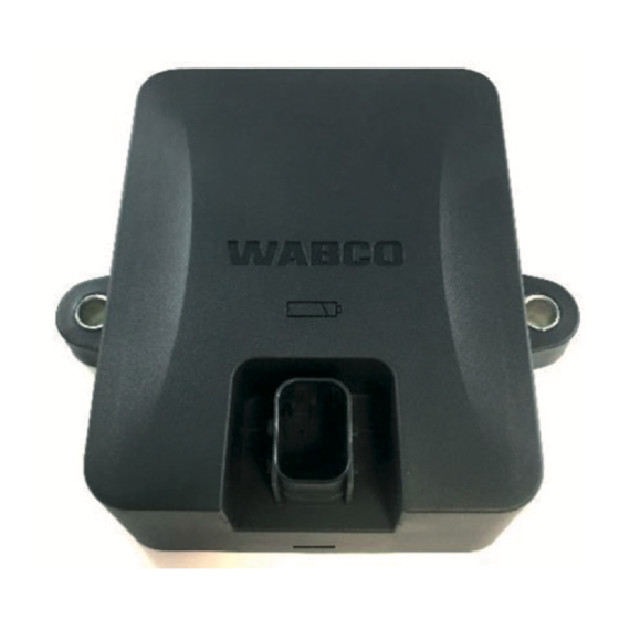
Introduction - Hardware Components Introduction - Hardware Components TRAILERCAST with Battery is a trailer tracking device with an embedded SIM card, GSM antenna and GPS antenna. It is designed for outside use. It has an RF antenna to be used for tire pressure monitoring. It is designed to be installed under the trailer. - Page 14 Introduction - Hardware Components Side view 4019847a Pin Assignment Device serial number: TPXX-XXXXXXXXXXXXXXX All WABCO component part number information can be found in Appendix II.
-
Page 15: Installation - Trailercast With Battery Position
„ the hardware unit. Always verify that sufficient GPS coverage is guaranteed during installation, and a good GPS position „ has been received via https://install.us.wabco-fleet.com/search/?device=trailercast. Check this for every installation. Preferred Installation (Standard Trailer with Fixed Trailer Bed) In case the installation includes a Tire Pressure Monitoring System (TPMS) system (connecting to the „... -
Page 16: Alternative Installation (In Case Of Trailer Without Fixed Trailer Bed)
(min. 150 cm). Keep the sides of the unit at a minimum distance of 20 cm from obstacles (also keep a minimum „ distance of 20 cm above the unit). Always verify that sufficient GPS coverage is guaranteed and a good GPS position has been received „ using https://install.us.wabco-fleet.com/search/?device=trailercast (Section 14 Checking the Installation, page 38). -
Page 17: Preferred Installation For Trailercast With Battery: Between Axle 2 And 3, Connector Upwards And To Back Of The Trailer
Installation – TRAILERCAST with Battery Position Preferred Installation for TRAILERCAST with Battery: Between Axle 2 and 3, Connector Upwards and to Back of the Trailer In case the installation includes a TPMS system (connecting to the internal sensors), an installation „... -
Page 18: Alternative Installation For Trailercast With Battery: Between Axle 1 And 2, Connector Upwards And To The Front Of The Trailer
Installation – TRAILERCAST with Battery Position Alternative Installation for TRAILERCAST with Battery: Between Axle 1 and 2, Connector Upwards and to the Front of the Trailer In case the installation includes a TPMS system (connecting to the internal sensors), an installation „... - Page 19 6.5.2 Installation Instructions for Cables The general installation instructions to be observed for cables and connectors can be downloaded from: http://inform.wabco-auto.com/intl/drw/9/4490000000.pdf. After connecting all hardware to TRAILERCAST with Battery, ZF recommends using cable ties to relieve tension from the connectors.
-
Page 20: Fastening Trailercast With Battery
TRAILERCAST with Battery on p. 14.) Always verify that sufficient GPS coverage is guaranteed and a good GPS position has been received using https://install.us.wabco-fleet.com/search/?device=trailercast (Section 14 Checking the Installation, page 38). Check this for every installation! Please observe the following recommendations: Install the unit centered between the wheels (in the middle of the axle). - Page 21 Fastening TRAILERCAST with Battery...
-
Page 22: Fastening Trailercast With Battery (When Bracket Is Not Used)
Fastening TRAILERCAST with Battery (when Bracket is not used) Fastening TRAILERCAST with Battery (when Bracket is not used) The installation of bracket is not required when no TPMS system is used. The 2 fixing points have a diameter of 8.8 mm. ZF recommends using M8 bolts or screws to mount the TRAILERCAST with Battery unit. When fastening TRAILERCAST with Battery on the vehicle (when bracket is not used), use 2 hexagon head bolts M8 x 1.25, class 8.8 and tighten the bolts with a maximum torque of 25.4 Nm (dry). -
Page 23: Connecting Hardware
Connecting Hardware Connecting Hardware Hardware Activation The TRAILERCAST with Battery unit is preactivated and will start sending positions as soon as the unit is connected to a power source (iABS or RSSplus). Connection to TRAILERCAST for iABS or RSSplus The connector on the specific iABS or RSSplus connection cable is connected to the iABS or RSS port of the TRAILERCAST with Battery unit. - Page 24 Connecting Hardware Plug the connector into the port. The design of the connector will help prevent you from plugging it in incorrectly. 4019857a Press down the connector. By pressing down the connector, the yellow clip will automatically move down. 4019858a Finally, press the yellow clip to lock the connection.
- Page 25 Connecting Hardware The connector has been plugged in correctly. 4019860a...
-
Page 26: Wabco Iabs Subsystems
WABCO iABS Subsystems WABCO iABS Subsystems 10.1 Hardware Connection 10.1.1 iABS 1M Premium/2M Standard/2M Premium In case of a modulator 1M premium (400 500 350 0) or 2M standard (400 500 420 0/400 500 425 0) or 2M premium (400 500 430 0), you can connect TRAILERCAST with Battery to the modulator SUBSYSTEMS port using the iABS connection cable. - Page 27 WABCO iABS Subsystems 10.1.2 iABS 1M standard (400 500 320 0) In case of a modulator 1M standard (400 500 320 0), since SUBSYSTEMS port is not available on the modulator, a power hub cable (894 600 151 2) which includes POWER and SUBSYSTEMS ports, can be used while connecting it to the power port of the modulator.
-
Page 28: Wabco Rss Subsystems
WABCO RSS Subsystems WABCO RSS Subsystems 11.1 Hardware Connection In case of RSSplus 2M (480 107 001 0) modulator, you can connect TRAILERCAST with Battery to the modulator SUBSYSTEMS port using the RSSplus adapter cable (449 913 050 0) and TRAILERCAST connection cable (894 600 001 2). -
Page 29: Connecting To The Internal Sensors
(see the following Section 13.3 Installation of the Internal Sensor, page 34). Internal Sensor – SMS Grey WABCO part number 960 733 001 0 Remember to write down the sensor IDs with the corresponding wheel positions when installing the sensors. Use the install form below. -
Page 30: Wabco Tpms Manager
2000 m 12.3.2 Purpose and Function The WABCO TPMS Manager can be used to stimulate and read WABCO SMS tire pressure sensor. Data such as temperature, pressure, lifetime of internal batteries, IDs, etc. can be read out. The WABCO TPMS manager can be configured in different languages via its menu. -
Page 31: Wabco Tpms Manager Software Update
PSI/ °C Fahrenheit Bar/ °F kPa/ °C PSI/ °F To control the internal sensor SMS, you may need to update the software version on the ZF WABCO TPMS Manager. 12.4 WABCO TPMS Manager Software Update Start the WebVT software. Connect the WABCO TPMS Manager to your PC using the supplied USB cable. - Page 32 Select an internal sensor (SMS) from the READ OUT SENSOR menu of the WABCO TPMS Manager. „ Hold the WABCO TPMS Manager close to the internal sensor, either from the side of the tire sidewall or „ from the tread.
-
Page 33: Assembly Of The Internal Sensor Sms
Replace the internal sensor if the pressure opening is blocked with foreign bodies. Use fastening straps that are approved for the corresponding rim size (see Section 13.3 Installation of the Internal Sensor, page 34, https://www.wabco-customercentre.com/catalog/docs/8150102293.pdf). Remember to write down the sensor IDs with the corresponding wheel positions when installing the sensors. -
Page 34: Preparing The Installation
Assembly of the Internal Sensor SMS 13.2 Preparing the Installation See Section 13.3 Installation of the Internal Sensor, page 34, https://www.wabco-customercentre.com/ catalog/docs/8150102293.pdf. Jack up the vehicle at the corresponding wheel positions. Remove the wheel. Use a suitable assembly device to remove the tire. - Page 35 Assembly of the Internal Sensor SMS Pass the Velcro through the ladder buckle. Tighten the fastening strap with a tensile force of ~100 Nm and close the Velcro fastener. The sensor must lie flat on the drop-center with the concave underside. The Velcro fastener must be pressed firmly over its length. The two layers of the Velcro fastener must lie flush on top of each other over the entire length (the Velcro fastener must not be pressed literally offset).
-
Page 36: Assembly Of The Tire
Assembly of the Internal Sensor SMS To better locate the sensor when mounted, secure the sensor at the height of the valve. Secure the Velcro fastener by pulling the plastic strap loop centrally onto the sewn end of the fastening strap. -
Page 37: Assembly Of The Wheel
Assembly of the Internal Sensor SMS Apply assembly fluid to the tire bead and rim flange. During assembly, the tire bead must not be pressed against the wheel electronics. Otherwise there is a risk that the internal sensor will be destroyed by the contact due to tensile or compressive forces. Make sure that a tire bead is not pressed onto or pulled over the sensor. -
Page 38: Checking The Installation
Scan the following QR code with your smartphone (a QR code reader app installed on your smartphone is required): On the WABCO Fleet Installer page, tap Scan QR code and scan the QR code on the TRAILERCAST with Battery device label (back/top side). - Page 39 Checking the Installation This procedure requires an active Internet connection on your smartphone. Before checking the data with WABCO Fleet Installer: Make sure iABS or RSSplus is not connected to the TOOLBOXPLUS™ software. Turn ON the vehicle contact. Select the Installation Wizard.
-
Page 40: Installation Wizard
Checking the Installation 14.1 Installation Wizard Identify the vehicle. Identify the vehicle by entering the parameters below: Vehicle Identification Number (VIN) „ iABS/ RSS Brand „ Trailer Utilization „ Trailer Manufacturer „ License Plate* „ Customer „ Number of axles „ Axle Brand „... - Page 41 Checking the Installation Battery Status: OK/Not OK. Check trailer to truck ISO connection cable. Verify that the telematics option for the iABS/RSS is enabled. Turn ON the vehicle contact. In case the Battery status is not OK, verify all cable connections from iABS/RSS to TRAILERCAST with Battery or truck to trailer are connected and powered.
- Page 42 Checking the Installation Axle load „ Mileage/Odometer „ Speed „ EBS/iABS/RSS Brand „ EBS/iABS/RSS Model „ History: Last received valid status. „ Press Next to continue. GPS status: OK/Not OK. Verify the GPS status: In case the GPS status is not OK, make sure that the position of TRAILERCAST with Battery meets the requirements (Step 6 - TRAILERCAST with Battery position).
- Page 43 Checking the Installation Use the TPMS manager (300 200 001 0) to simulate the sensor to make it visible and/or read the „ sensor ID. Repeat these steps until a sensor has been assigned to all tires. „ Create and send a report Email. Send a report via email to confirm the installation. Enter the required parameters: Email address „...
- Page 44 Checking the Installation Press Send to complete the process.
-
Page 45: Vehicle Electrical Grounding Guidelines
Appendix I Appendix I 15.1 Vehicle Electrical Grounding Guidelines Ensure that the vehicle includes a correct common chassis ground point. A common chassis ground point connects the trailer frame/chassis to the ground pin of the J560 seven-way connector and will help protect the vehicle electrical system from unwanted electrical noise. -
Page 46: Parts And Variant List
Appendix II Appendix II 16.1 Parts and Variant List ABS VARIANT LIST 4019747a 4019746a 4019747a 4019745a 2S/2M Pull 2S/2M to 4S/3M 4019749a Variants 2S/1M Standard 2S/1M Premium 2S/2M Standard Trailer Premium Part Number 400 500 320 0 400 500 350 0 400 500 420 0 400 500 425 0 400 500 430 0... - Page 47 Appendix II RSSplus VARIANT LIST Variants RSSplus 4S/2M Part Number 480 107 001 0 CAN Capable Subsystems Port PARTS LIST Slot on RSSplus Modulator Application Part Number Length 449 351 010 0 449 351 047 0 4.7 M Power Power Cable 449 913 050 0 Subsystem TRAILER CAST –...
- Page 48 CVS unites ZF’s former Commercial Vehicle Technology and Commercial Vehicle Control Systems divisions, the latter being formed following ZF’s acquisition of WABCO in Spring 2020. For more information, visit: www.zf.com/cv © 2022 ZF CV Systems North America LLC – All Rights Reserved – TP2205 / 10.2022...
Need help?
Do you have a question about the TP2205 and is the answer not in the manual?
Questions and answers