Table of Contents
Advertisement
Quick Links
Advertisement
Table of Contents

Summarization of Contents
1. INTRODUCTION
1.1 INTENDED USE
Camera system designed for technicians, engineers, and scientists for scientific measurements.
1.2 FORESEEABLE MISUSE
Warning about operating with excessive light input to prevent damage to the image intensifier.
1.3 SCHEMATIC SKETCH
Diagram illustrating the components of an intensified PCO camera.
2. SAFETY INSTRUCTIONS
General Safety Precautions
Covers laser, electric shock, tripping, humidity, dust, radiation, shock, vibration, liquid, and housing damage risks.
Lens Mounting Safety
Instructions for safely mounting the lens to avoid thread or mount damage.
2.1 SAFE USE OF IMAGE INTENSIFIER
Guidelines to prevent damage to the image intensifier from overexposure and light.
3. SYSTEM COMPONENTS
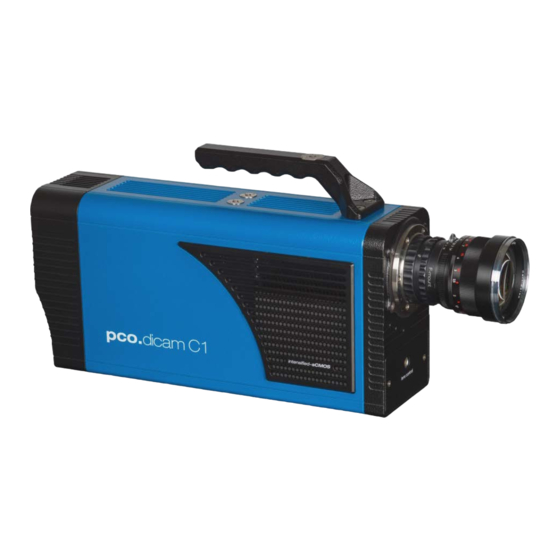
3.1 SYSTEM COMPONENTS PCO.DICAM C1
Lists all parts included in the pco.dicam C1 camera system.
3.2 SYSTEM COMPONENTS PCO.DICAM C4
Lists all parts included in the pco.dicam C4 camera system.
4. INSTALLATION
4.1 DRIVER INSTALLATION
Instructions for installing drivers and software for camera operation via USB drive.
Graphic Card NVIDIA Cuda Driver
Guidance on updating NVIDIA drivers for optimal GPU Processing in pco.camware.
4.2 CAMWARE INSTALLATION
Step-by-step guide to installing the pco.camware application software.
5. FIRST START
5.1 PREPARATION
Checks and setup steps required before powering on and operating the camera.
5.2 STARTING THE SYSTEM
Instructions on launching the pco.camware software and its graphical user interface.
5.3 ACQUIRING THE FIRST IMAGE
Procedure to acquire and display the first image, including initial settings.
6. TIMING PCO.DICAM C1
6.1 SINGLE IMAGE MODE TIMING
Explains the timing diagram and principles for acquiring single images with the pco.dicam C1.
6.2 DOUBLE IMAGE MODE TIMING
Details the timing for acquiring two consecutive images with configurable interframing times.
7. TIMING PCO.DICAM C4
7.1 MASTER VS INDIVIDUAL CHANNEL TRIGGER
Compares Master Trigger and Individual Channel Triggering methods for the pco.dicam C4.
7.2 SINGLE IMAGE MODE 4 CHANNELS
Explains burst mode timing for four channels in single image acquisition using Master Trigger.
7.3 DOUBLE IMAGE MODE 4 CHANNELS
Details burst mode timing for four channels in double image acquisition using Master Trigger.
8. CAMWARE SOFTWARE
8.1 TIMING CONFIGURATION
How to configure timing parameters such as delay and exposure in pco.camware.
8.2 SENSOR CONTROL
Settings for sensor control, including Double Image mode activation.
8.3 INTENSIFIER CONTROL
Adjusting intensifier voltage and gating mode for optimal performance and safety.
8.4 HARDWARE I/O CONTROL PCO.DICAM C1
Configuration of hardware input/output signals for the pco.dicam C1.
8.5 HARDWARE I/O CONTROL PCO.DICAM C4
Configuration of hardware input/output signals for the pco.dicam C4.
9. SPECIAL FEATURES PCO.DICAM C4
9.1 COMMON TIME PROPERTIES
Simplifies setup by setting common parameters for all four cameras.
9.1.1 SINGLE IMAGE MODE TIMING
Configuring timing for all channels in single image mode using Common Time Properties.
9.1.2 DOUBLE IMAGE MODE TIMING
Configuring timing for all channels in double image mode using Common Time Properties.
9.1.3 WITHOUT COMMON SETTINGS
Advanced mode for individual channel timing setup without constant exposure times.
9.2 CAMERA MENU AND FUNCTIONS
Accessing camera functions like acquisition, control, and beam splitter adjustment.
9.3 MATCHING THE 4 IMAGE INTENSIFIERS
Procedure for adjusting individual channel settings for homogeneous intensity results.
A1 TECHNICAL DATA PCO.DICAM C1
A1.1 MECHANICAL DIMENSIONS
Detailed mechanical dimensions of the pco.dicam C1 in millimeters.
A1.2 SPECIFICATIONS
Technical specifications for the SCMOS sensor, image intensifier, and general camera features.
A1.3 REAR PANEL CONNECTORS
Description of connectors and ports on the rear panel of the pco.dicam C1.
A2 TECHNICAL DATA PCO.DICAM C4
A2.1 MECHANICAL DIMENSIONS
Detailed mechanical dimensions of the pco.dicam C4 in millimeters.
A2.2 COLLIMATING LENS MOUNTING
Instructions for mounting the collimating lens in front or side positions.
A2.3 SPECIFICATIONS
Technical specifications for the SCMOS sensor, image intensifier, and general camera features.
A2.4 REAR PANEL CONNECTORS
Description of connectors and ports on the rear panel of the pco.dicam C4.
A3 ADAPTER / ACCESSORIES
A3.1 PCO.TRIGGER UNIT
Details the pco.trigger unit for generating and adjusting trigger signals.
A3.2 PCO F-MOUNT ADAPTER
Information on the F-mount adapter and matching lenses with automatic diaphragm.
A3.3 MOUNT CONVERSION F-TO-C
Procedure for changing the optical input from F-mount to C-mount.
A4 KAYA FRAME GRABBER INSTALLATION
A4.1 INTRODUCTION & SYSTEM REQUIREMENTS
Introduction to Kaya frame grabber installation and its system requirements.
A4.3 SAFETY INSTRUCTIONS
Safety guidelines for frame grabber installation, including laser and electric shock warnings.
A4.4 FRAME GRABBER INSTALLATION
Step-by-step instructions for installing the Kaya Camera Link HS grabber card.
A4.5 VISION POINT SOFTWARE
Using Vision Point software to check hardware and firmware information.
A4.6 UPDATE GRABBER FIRMWARE
Procedure for updating the firmware of the Kaya frame grabber card.
A6 CUSTOMER SERVICE
A6.1 SERVICE AND MAINTENANCE
Information on camera service, cleaning guidelines, and protective cap usage.
A6.3 RECYCLING
Instructions for proper disposal and recycling of the camera.
A6.4 TROUBLE SHOOTING AND SUPPORT
Guide to creating logfiles and support files for PCO technical support.


Need help?
Do you have a question about the dicam C4 and is the answer not in the manual?
Questions and answers