Advertisement
Quick Links
Installation and Service Instructions
MADE
in the
USA
• In the United States, installation must conform with local codes
or in the absence of local codes, with the National Fuel Gas
Code, ANSI Z223.1-latest edition available from American
National Standard Institute. Further reference should be made
to the recommendation of your fuel supplier.
• In Canada, installation must conform with local codes or in the
absence of local codes, with Installation Codes for Gas Burning
Appliances and Equipment, CGA Standard CAN/CGA 1-B-149.1
or 2.
•
WARNING: Additions, changes, conversions
and service must be performed by an authorized Midco
representative, service agency or the fuel supplier. Use
only MIDCO specifi ed and approved parts.
• INSTALLER: Inform and demonstrate to the user the correct
operation and maintenance of the gas utilization equipment.
Inform the user of the hazards of storing fl ammable liquids
and vapors in the vicinity of this gas utilization equipment
and remove such hazards. Affi x this manual and associated
literature to the burner.
CODE COMPLIANCE IS THE SOLE
RESPONSIBILITY OF THE INSTALLER.
• USER: Retain this manual for future reference. If other than
routine service or maintenance as described in this manual
and associated literature is required, contact a qualifi ed service
agency. DO NOT ATTEMPT REPAIRS. An inadvertent service
error could result in a dangerous condition.
AVOID ERROR IN PARTS SELECTION. When ordering use complete MIDCO
Part Number and Description. Furnish Burner Model Number, Bill of Material
Number and Serial Number (if available) from the specifi cation plate found on the
product.
IMPORTANT: Availability of parts as well as specifi cations are subject to change
without notice. Please consult factory for item availability.
®
Midco
International Inc.
4140 West Victoria Street
Chicago, Illinois 60646
toll free 866.705.0514
tel
773.604.8700
fax
773.604.4070
web
www.midcointernational.com
e-mail sales@midcointernational.com
SAFETY INFORMATION TERMS: The following terms are used to identify hazards, safety precaution of special notations
and have standard meanings throughout this manual. They are printed in all capital letters using a bold type face as shown
below, and preceded by the exclamation mark symbol. When you see the safety alert symbol and one of the safety information
terms as shown below, be aware of the hazard potential.
DANGER:
Identifi es the most serious hazards which will result in severe personal injury or death.
WARNING:
Signifi es a hazard that could result in personal injury or death.
CAUTION:
Identifi es unsafe practices which would result in minor personal injury or product and property
damage.
Quality Designed for Proven Performance
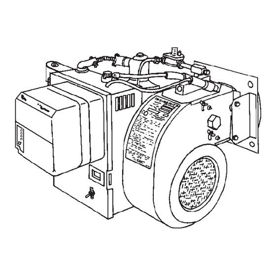
Incinomite
J81A-3 and J121A-3
Incinerator Gas Burners
The INCINOMITE Models J81A-3 and J121A-3 incinerator gas
burners feature continuously monitored electronic fl ame safety
and spark ignited intermittent proven ignitor (pilot). They are
adaptable to either primary or secondary chamber installation.
WARNING: If the information in these instructions
is not followed exactly, a fi re or explosion may result,
causing property damage, personal injury or death.
Do not store or use gasoline or other fl ammable vapors and
liquids in the vicinity of this or any other appliance.
WHAT TO DO IF YOU SMELL GAS:
•
Do not try to light any appliance.
•
Do not touch any electrical switch; do not use any
phone in your building.
•
Immediately phone your gas supplier from another
building. Follow the gas supplier's instructions. If
you cannot reach your gas supplier call the fi re
department.
Installation and service must be performed by a qualifi ed
installer, service agency or the gas supplier.
BURNER MODEL:
___________________________________
BILL OF MATERIAL
NUMBER:
___________________________________
SERIAL NUMBER #: ___________________________________
WIRING DIAGRAM: ___________________________________
FOR SERVICE CONTACT
Name:
____________________________________________
Address: ____________________________________________
____________________________________________
Phone:
____________________________________________
Date of Installation: ___________________________________
917
8470 70
Printed in USA
Advertisement

Related Manuals for Midco Incinomite J121A-3


Summarization of Contents
Specifications and Installation Details
Burner Air Delivery and Gas Pressure Specifications
Technical specifications for burner air flow rates and minimum gas pressure settings for input adjustment.
Burner Firing Rate and Maximum Input Capacities
Details on burner firing rates for natural and propane gas, including maximum input with varying air conditions.
Electrical Supply and Control Component Specifications
Electrical requirements, burner on-off control, flame safety, and optional accessories like weatherhoods.
Primary Chamber Fuel Input Requirements
Waste Material Categories for Primary Chamber Fuel
Defines and categorizes different types of waste materials (No. 1 to No. 4) for primary chamber fuel input.
Installation Procedures
Indoor Ventilation and Combustion Air
Ensuring adequate ventilation in the incinerator room for combustion air supply and avoiding negative pressure.
Burner Mounting and Flange Adjustment
Guidelines for burner placement, adjusting the mounting flange for different firing angles, and pre-mounting checks.
Down Draft Design Gas Leak Venting
Specific caution for down draft designs requiring a direct draft vent opening for gas leakage.
Chimney, Venting, and Piping
Chimney Draft Control and Damper Installation
Requirements for barometric and fixed dampers based on chimney height to control draft.
Gas Supply Piping and Regulator Installation
Instructions for gas piping, joint compound, main gas pressure regulators, and pressure limits.
Electrical Wiring and Connections
Electrical Codes and Wiring Safety
Conforming to electrical codes, using correct wiring, and safety precautions for cooling systems.
Wiring Diagram and Remote Control Usage
Information on the wiring diagram and safe operation of remote switches or timers.
Initial Startup and Adjustment Procedures
Pre-Startup Checks and Gas Leak Testing
Steps for checking burner piping, valves for gas leaks, and verifying initial settings before ignition.
Ignitor Trial, Flame Adjustment, and Troubleshooting
Procedures for igniting the pilot, adjusting the ignitor regulator, and troubleshooting ignition failures.
Main Flame Adjustment and Firing Rates
Adjusting Main Flame Input and Using Firing Curves
Guidance on adjusting the main gas input and utilizing firing rate curves for specific gas pressures.
Ignitor and Regulator Assembly Service
Ignitor Assembly Removal and Ignition Troubleshooting
Procedures for removing the ignitor/regulator and common causes of ignition problems.
Final Startup Checks and Shutdown
Verifying blower air shutter, gas firing rate, controls, and proper burner shutdown procedures.
Ignitor Components and Gas/Air Adjustments
Ignitor Assembly Components and Electrode Checks
Details on ignitor parts, electrode positioning, air deflector angle, and wire insulation inspection.
Ignitor Firing Rate and Gas Orifice Specifications
Information on ignitor firing rates, orifice sizes, and recommended gas pressures for different models.
Ignitor Air Adjustment and Flame Safeguard Operation
Ignitor Air Adjustment Procedure for J121A-3
Step-by-step instructions for adjusting the ignitor air screw for optimal flame on J121A-3 models.
Honeywell RM7890 Flame Safeguard System
Overview of the RM7890 system, its LEDs, sequences, and critical safety warnings.
Flame Safeguard Sequences and Special Equipment
Ignition Trial, Run, and Sequence States
Details on ignition trial phases, run mode, standby mode, and sequence states of the flame safeguard.
Handling Special Equipment and OEM Variations
Guidance for variations due to special factory/field equipment and high/low gas pressure switches.
Main Automatic and Ignitor Gas Valve Function
Description of single function on-off gas valves and conditions requiring replacement.
Blower Assembly Motor Maintenance
Information on blower motor types, overload protection, interlocks, and maintenance procedures.
Troubleshooting Guide
Thermal Switch Function and Testing
Explanation of the thermal switch's role and procedures for testing its continuity.
Motor Not Running Electrical Diagnostics
Diagnostic steps for motor failure, focusing on electrical checks and voltage confirmation.
No Flame / Motor Running Troubleshooting
Troubleshooting steps for no flame with motor running, including voltage, gas pressure, and spark checks.
Continued Troubleshooting
Ignitor Flame and Main Flame Issues
Troubleshooting for ignitor flame only, ignitor lighting without main flame, and flame quality issues.
Gas Failure to Shut Off Diagnosis
Diagnosing issues where gas fails to shut off, including valve defects and high gas pressure.
Need help?
Do you have a question about the Incinomite J121A-3 and is the answer not in the manual?
Questions and answers