Table of Contents
Advertisement
Installation and Service Instructions
•
In the United States, installation must conform with local
codes or in the absence of local codes, with the National
Fuel Gas Code, ANSI Z223.1-latest edition available from
American National Standard Institute. Further reference
should be made to the recommendation of your fuel supplier.
•
In Canada, installation must conform with local codes or in
the absence of local codes, with Installation Codes for Gas
Burning Appliances and Equipment, Standard CAN/CGA
1-B-149.1 or 2.
!
•
WARNING: Additions, changes, conversions and
service must be performed by an authorized Midco
representative, service agency or the fuel supplier. Use
only MIDCO specifi ed and approved parts.
•
INSTALLER: Inform and demonstrate to the user the correct
operation and maintenance of the gas utilization equipment.
Inform the user of the hazards of storing fl ammable liquids
and vapors in the vicinity of this gas utilization equipment
and remove such hazards. Affi x this manual and associated
literature to the burner.
•
CODE COMPLIANCE IS THE SOLE RESPONSIBILITY OF
THE INSTALLER.
•
USER: Retain this manual for future reference. If other than
routine service or maintenance as described in this manual
and associated literature is required, contact a qualifi ed
service agency. DO NOT ATTEMPT REPAIRS.
An inadvertent service error could result in a dangerous
condition.
Midco® International Inc.
4140 West Victoria Street
Chicago, Illinois 60646
toll free 866.705.0514
tel
773.604.8700
fax
866.580.8700
web
www.midcointernational.com
e-mail sales@midcointernational.com
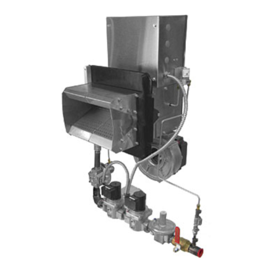
Unipower VA Series
120 Volt Variable Air Gas Burners - Models V1 to V10
24 Volt Variable Air Gas Burners - Models V1 and V2
Safety INFORMATION TERMS: The following terms are used to identify hazards, safety precaution of special
notations and have standard meanings throughout this manual. They are printed in all capital letters using a
bold type face as shown below, and preceded by the exclamation mark symbol. When you see the safety alert
symbol and one of the safety information terms as shown below, be aware of the hazard potential.
DANGER:
Identifi es the most serious hazards which will result in severe personal injury or death.
!
WARNING:
Signifi es a hazard that could result in personal injury or death.
CAUTION:
Identifi es unsafe practices which would result in minor personal injury or product and
property damage.
Quality Designed for Proven Performance
!
WARNING: If the information in these instructions
is not followed exactly, a fi re or explosion may result,
causing property damage, personal injury or death.
Do not store or use gasoline or other fl ammable vapors and
liquids in the vicinity of this or any other appliance.
WHAT TO DO IF YOU SMELL GAS:
•
Do not try to light any appliance.
•
Do not touch any electrical switch; do not use any phone in
your building.
•
Immediately phone your gas supplier from another building.
Follow the gas supplier's instructions. If you cannot reach
your gas supplier call the fi re department.
Installation and service must be performed by a qualifi ed
installer, service agency or the gas supplier.
BURNER MODEL: _____________________________________
BILL OF MATERIAL
NUMBER: ____________________________________________
SERIAL NUMBER #: ___________________________________
WIRING DIAGRAM: ____________________________________
FOR SERVICE CONTACT
Name:
____________________________________________
Address: ____________________________________________
____________________________________________
Phone:
____________________________________________
Date of Installation: ___________________________________
AVOID ERROR IN PARTS SELECTION. When ordering use
complete MIDCO Part Number and Description. Furnish Burner
Model Number, Bill of Material Number and Serial Number (if avail-
able) from the specifi cation plate found on the product
IMPORTANT: Availability of parts as well as specifi cations are
subject to change without notice. Please consult factory for item
availability.
420C
U
L
US
US
8471 95
C
®
Printed in USA
Advertisement
Table of Contents

Related Manuals for Midco Unipower VA Series


Summary of Contents for Midco Unipower VA Series
- Page 1 1-B-149.1 or 2. SERIAL NUMBER #: ___________________________________ • WARNING: Additions, changes, conversions and service must be performed by an authorized Midco WIRING DIAGRAM: ____________________________________ representative, service agency or the fuel supplier. Use only MIDCO specifi ed and approved parts. FOR SERVICE CONTACT •...
- Page 2 1.75 1.75 Standard burners are shipped as NATURAL gas models. Contact Midco for PROPANE gas burners. 1 MBH = 1,000 Btu/hr All Ratings Based on 1000 BTU/Cu. Ft. NATURAL, 2500 BTU/Cu. Ft. PROPANE at sea level. Derate burner for altitude over 2,000 feet by 4% for each 1,000 feet above sea level.
- Page 3 Part 1 Installation CAUTION: The Unipower VA Series burners are not intended for outdoor installation Part 1 and must be protected from excessive moisture. Provide adequate clearance for Installation service and proper operation. When installed indoors, the area must be checked for proper ventilation before installing.
- Page 4 1 ¼ ″ Propane 1040 pressure drop of 0.5″ W.C.. For higher 1 ½ ″ Natural 900 permissible pressure drops, consult your gas supplier. 1 ½ ″ Propane Table 2: Schedule 40 NPT Pipe - Capacity Chart 8471 95 Midco International Inc.
- Page 5 The frame of the burner should be well grounded. Normally the piping and/or electric conduit will provide suffi cient grounding. However, a ground lug is located in control box for positive grounding where insulated pipe couplings are used or where any doubt exists regarding grounding suffi ciency. 8471 95 Midco International Inc.
- Page 6 (Optional) Gas pressure switch and proof of closure wiring: If applicable, connect the wires from the gas pressure switches and/or proof of closure switch to the corresponding terminals inside the control box. Refer to the wiring diagram inside the control box door for additional information. 8471 95 Midco International Inc.
- Page 7 JUMPERS RELAY LOW A/S R/BK IGNITION TRANSFORMER SCEBM-2 INPUT2 BR/W PILOT GAS VALVE LEGEND SOLID WIRING AND SCEBM-2 COMPONENTS BY MIDCO INPUT1 BL/W RELAY DASHED WIRING AND SOCKET COMPONENTS BY INSTALLER MAIN GAS VALVES BL/W ENCIRCLED: FLAME SAFEGUARD SOLID ROUND:...
- Page 8 UV SCANNER LOW A/S R/BK IGNITION TRANSFORMER SCEBM-2 INPUT2 BR/W PILOT GAS VALVE LEGEND SOLID WIRING AND SCEBM-2 COMPONENTS BY MIDCO INPUT1 BL/W RELAY DASHED WIRING AND SOCKET COMPONENTS BY INSTALLER MAIN GAS VALVES BL/W ENCIRCLED: FLAME SAFEGUARD SOLID ROUND:...
- Page 9 P74 - Post purging LEGEND 13 R/W HIGH A/S oP - Operation, modulating SOLID WIRING AND LOW A/S operation COMPONENTS BY MIDCO R/BK DASHED WIRING AND .oP - Present output, % COMPONENTS BY INSTALLER FL. - Flame current, % SOLID ROUND: TERMINAL...
- Page 10 BL or W P74 - Post purging LEGEND 13 R/W HIGH A/S oP - Operation, modulating SOLID WIRING AND LOW A/S operation COMPONENTS BY MIDCO R/BK (2)NO DASHED WIRING AND .oP - Present output, % (3)C (2)NO COMPONENTS BY INSTALLER (3)C FL.
- Page 11 BL/W BL/W 24V RELAY LEGEND SOLID WIRING AND COMPONENTS LOW A/S R/BK BY MIDCO DASHED WIRING AND COMPONENTS BY INSTALLER SUPPLIED BY MIDCO INSTALLED BY OTHERS BLOWER SCEBM-1 ENCIRCLED: IGNITION CONTROL BLOWER SCEBM-1 SOLID ROUND: TERMINAL STRIP BLOWER SCEBM-1 OPEN ROUND: COMPONENT...
- Page 12 If light is not visible through all of the holes, then the low fi re is too low and the low fi re bypass located on the side of the ratio regulator, see Figure 9 item # 6, needs to be opened (counter-clockwise to open, clockwise to close). __________________________________________ 8471 95 Midco International Inc.
- Page 13 MAXIMUM INLET PRESSURE: 14” W. C. BTU/HR MAX. CAPACITY: MINIMUM FIRING RATE: BTU/HR PRESSURE REQUIRED: W.C. 10” MANIFOLD PRESSURE W.C. VOLTS AMPS CONTROLS ® MOTOR ® LISTED 2121-07 CHICAGO, IL 60646 No. Pl-100, 058 Figure 7 Burner Rating Label _____________________________________ 8471 95 Midco International Inc.
- Page 14 V9 - V10 V5 - V6 V3 - V4 Manifold Pressure (Inches W.C.) 1000 1500 2000 2500 3000 3500 4000 Firing Rate (mbtu/hr) Chart 1 - Manifold Pressure vs. Firing Rate - VA 120V Burners 8471 95 Midco International Inc.
- Page 15 Modulate the burner to high fi re by applying a 10V DC input signal. Verify that the manifold pressure is the same as marked on the Burner Rating Label(s) for the actual fi ring rate. __________________________________________ 8471 95 Midco International Inc.
- Page 16 Turn on power switch on burner control panel door Set heat enable and temperature controller to desired operating condition and temperature 24V Burners Burner will start and operate based on 2 to 10V DC analog input provided _____________________________________ 8471 95 Midco International Inc.
- Page 17 The temperature control or operating control sends a heat input signal (2-10 VDC) to the blower; as a result, the blower pressure causes the gas to modulate through the ratio regulator. __________________________________________ 8471 95 Midco International Inc.
- Page 18 Burner begins modulating based on 2-10 VDC modulating signal Heat Satisfi ed: • Operating control opens • All components shut off • SCEBM-2 control will read “OFF” Chart 4 - Intermittent 120-V Sequence of Operation 8471 95 Midco International Inc.
- Page 19 Burner begins modulating based on 2-10 VDC control signal Heat Satisfi ed: • Operating control opens • All components shut off • SCEBM-2 control will read “OFF” Chart 5 - Interrupted 120V Sequence of Operation __________________________________________ 8471 95 Midco International Inc.
- Page 20 SCEBM-1 Control will shine solid green if DC signal is above 2 DCV • Burner begins modulating based on 2-10 VDC modulating signal Heat Satisfi ed • Operating control opens • All components shut off Chart 6 - 24V Sequence of Operation __________________________________________ 8471 95 Midco International Inc.
- Page 21 RUN=Run mode. After the ignition sequence is complete, the burner will be in run mode. Only in this mode will the combustion blower modulate based on the 2-10V DC temperature control signal. Table 4 - SCEBM-2 Modulating Settings for 120V Burners _____________________________________ 8471 95 Midco International Inc.
- Page 22 The password may either be enabled or disabled. dAbL tS: Allows the user to use the built-in onboard setpoint PASS and ignores the 2-10V input EnAb View the software version number. Chart 7 - Menu Map - 120V Burners __________________________________________ 8471 95 Midco International Inc.
- Page 23 VA series burners that use an intermittent pilot. vA-B is for VA series burners that use an interrupted pilot. Setting the noX is for Midco Low-NOx series burners. Parameters tLo and thi Use these parameters to adjust the minimum and maximum temperature set point that a user can set while outside of programming mode.
- Page 24 5. Pilot regulator vent clogged. 6. Defective main gas valve. 7. Low gas pressure. 8 . Insuffi cient pilot fl ame signal. BURNER DOES NOT LIGHT Direct Spark 1. Refer to page 25 for Siemens Lock/Error Codes 8471 95 Midco International Inc.
- Page 25 - Maximum speed = 0 rpm Loc: 227 Loc 227 Faulty PWM fan One or several parameters violate the minimum/ maximum limit Chart 8 - Siemens Control - Lock Codes - Error Code List - 120V Burners 8471 95 Midco International Inc.
- Page 26 Part 2 Service - Trouble Shooting for 120V Burners Trouble Shooting for 120V Burners Continued Siemens Control Sequence of Operation for 120V Burners Chart 9 - Siemens Control - Sequence of Operation - 120V Burners 8471 95 Midco International Inc.
- Page 27 NOTE: For meaning of the error and diagnostic codes, see Error code list in Chart 8 Shooting for 120V Burners Continued Siemens Control Display of Flame Current for 120V Burners Chart 10 - Siemens Control - Display of Flame Current - 120V Burners __________________________________________ 8471 95 Midco International Inc.
- Page 28 4. Pilot regulator defective. 5. Defective Ignition Control Module. 6. Defective main gas valve. 7. Low gas pressure. 8. Grossly mis-adjusted main gas and air mixture. 9 . Insuffi cient pilot fl ame sensing signal. __________________________________________ 8471 95 Midco International Inc.
- Page 29 Pilot Gas Regulator Air Pressure Tap Pilot Gas Manifold Pressure Tap 8416-14 Low Fire By Pass 2117-10 Variable Speed Blower 8416-04 Dungs FRG Ratio Regulator 16A 8402-00 Pilot Solenoid Valve 16B 8402-50 Pilot Solenoid Valve 8471 95 Midco International Inc.
- Page 30 Main Gas Solenoid Valve 2 8416-05 Main Gas Regulator 8404-67 Main Manual Gas Shut-off Valve Supply Gas Pressure Tap 8400-00 Pilot Gas Regulator Pilot Gas Manifold Pressure Tap 2117-10 Variable Speed Blower 8402-37 Pilot Solenoid Valve 8471 95 Midco International Inc.
- Page 31 8699-30 Air Pressure Pickup Tube 8433-24 Spark Rod 2112-01 Pilot 8433-25 Flame Rod 8699-30 Pilot Gas Line 8699-30 Air Pressure Tubing to Air Switch Not Shown 8456-07 High Voltage Spark Wire 8484-24 Flame Sensing Wire 8471 95 Midco International Inc.
- Page 32 8699-30 Air Pressure Pickup Tube 8433-24 Spark Rod 2112-01 Pilot 8433-25 Flame Rod 8699-30 Pilot Gas Line 8699-30 Air Pressure Tubing to Air Switch Not Shown 8456-07 High Voltage Spark Wire 8484-24 Flame Sensing Wire 8471 95 Midco International Inc.
- Page 33 Item # Part # Descriptions 2112-01 Pilot 8433-25 Flame Rod 8433-24 Spark Rod Burner Gas Manifold Gas Orifi ces 2122-10 High Temperature Flange Gasket 2113-50 Side Plate Main Gas Manifold Pressure Tap 2110-00 Baffl e 8471 95 Midco International Inc.
- Page 34 Figure 14 - Internal View of Burner Housing Front - 24V Burner Item # Part # Descriptions 2112-01 Pilot 8433-25 Flame Rod 8433-24 Spark Rod Main Gas Manifold Pressure Tap 2113-50 Side Plate 2110-00 Baffl e 2122-10 High Temperature Flange Gasket 8471 95 Midco International Inc.
- Page 35 Pilot Solenoid Valve 8409-25 Terminal Block 8406-98/99 Relay “B” 8406-95/96 Relay “A” 8425-56 Air Pressure Switch 8423-05 On/Off Switch 9A 8447-22 Ignition Transformer 9B 8447-39 Ignition Transformer 10A 8429-69 Ignition Control 10B 8429-93 Ignition Control (UV) 8471 95 Midco International Inc.
- Page 36 SCEBM - 1 8447-34 100VA Main 24VAC Transformer 8406-58 24VAC Relay 8408-78 120VAC Terminal Strip 8406-83 Nine Second Relay Timer 10. 8402-37 Pilot Solenoid Valve 11. 8425-56 Air Pressure Switch High/Low 12. 8423-05 On/Off Switch __________________________________________ 8471 95 Midco International Inc.
- Page 37 To shut off Close manual gas cock. Turn burner power OFF. Should overheating of the appliance occur Close the manual gas valve to the appliance. Do Not shut off the electrical supply power to the blower ________________________________________ 8471 95 Midco International Inc.
- Page 38 If a part is defective due to workmanship or materials and the part is removed from the product within the applicable warranty period and returned to Midco in accordance with the procedure described below, Midco will at its option either repair or replace the part.
- Page 39 Final disposition of any warranty claim will be determined solely by Midco. If an inspection by Midco does not disclose any defect covered by this warranty, the product will be returned, scrapped, repaired, or replaced as instructed by the customer. Products returned to the customer will be sent shipping charges collect.
- Page 40 FOLD LINE PLACE STAMP HERE Midco International Inc. Attn: Warranty Department 4140 West Victoria Street Chicago, Illinois 60646 FOLD LINE As an ISO 9001 certifi ed company, we proudly design, manufacture and assemble our products in Chicago, Illinois, USA. 420C 9001 ®...
Need help?
Do you have a question about the Unipower VA Series and is the answer not in the manual?
Questions and answers