Download Print this page
Midco Incinomite J81A-3 Installation And Service Instructions Manual

Midco Incinomite J81A-3 Installation And Service Instructions Manual

Incinerator gas burners

Advertisement

Quick Links

Installation and Service Instructions
MADE
in the
USA
• In the United States, installation must conform with local codes
or in the absence of local codes, with the National Fuel Gas
Code, ANSI Z223.1-latest edition available from American
National Standard Institute. Further reference should be made
to the recommendation of your fuel supplier.
• In Canada, installation must conform with local codes or in the
absence of local codes, with Installation Codes for Gas Burning
Appliances and Equipment, CGA Standard CAN/CGA 1-B-149.1
or 2.
WARNING: Additions, changes, conversions
and service must be performed by an authorized Midco
representative, service agency or the fuel supplier. Use
only MIDCO specifi ed and approved parts.
• INSTALLER: Inform and demonstrate to the user the correct
operation and maintenance of the gas utilization equipment.
Inform the user of the hazards of storing fl ammable liquids
and vapors in the vicinity of this gas utilization equipment
and remove such hazards. Affi x this manual and associated
literature to the burner.
CODE COMPLIANCE IS THE SOLE
RESPONSIBILITY OF THE INSTALLER.
• USER: Retain this manual for future reference. If other than
routine service or maintenance as described in this manual
and associated literature is required, contact a qualifi ed service
agency. DO NOT ATTEMPT REPAIRS. An inadvertent service
error could result in a dangerous condition.
AVOID ERROR IN PARTS SELECTION. When ordering use complete MIDCO
Part Number and Description. Furnish Burner Model Number, Bill of Material
Number and Serial Number (if available) from the specifi cation plate found on the
product.
IMPORTANT: Availability of parts as well as specifi cations are subject to change
without notice. Please consult factory for item availability.
®
Midco
International Inc.
4140 West Victoria Street
Chicago, Illinois 60646
toll free 866.705.0514
tel
773.604.8700
fax
773.604.4070
web
www.midcointernational.com
e-mail sales@midcointernational.com
SAFETY INFORMATION TERMS: The following terms are used to identify hazards, safety precaution of special notations
and have standard meanings throughout this manual. They are printed in all capital letters using a bold type face as shown
below, and preceded by the exclamation mark symbol. When you see the safety alert symbol and one of the safety information
terms as shown below, be aware of the hazard potential.
DANGER:
Identifi es the most serious hazards which will result in severe personal injury or death.
WARNING:
Signifi es a hazard that could result in personal injury or death.
CAUTION:
Identifi es unsafe practices which would result in minor personal injury or product and property
damage.
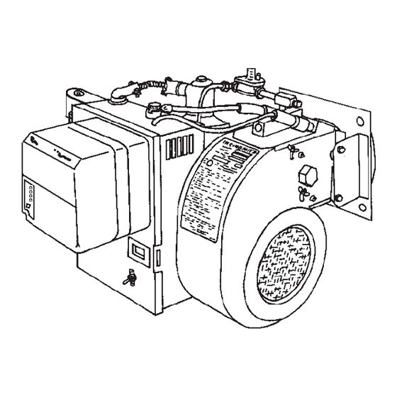
Quality Designed for Proven Performance
Incinomite
J81A-3 and J121A-3
Incinerator Gas Burners
The INCINOMITE Models J81A-3 and J121A-3 incinerator gas
burners feature continuously monitored electronic fl ame safety
and spark ignited intermittent proven ignitor (pilot). They are
adaptable to either primary or secondary chamber installation.
WARNING: If the information in these instructions
is not followed exactly, a fi re or explosion may result,
causing property damage, personal injury or death.
Do not store or use gasoline or other fl ammable vapors and
liquids in the vicinity of this or any other appliance.
WHAT TO DO IF YOU SMELL GAS:
Do not try to light any appliance.
Do not touch any electrical switch; do not use any
phone in your building.
Immediately phone your gas supplier from another
building. Follow the gas supplier's instructions. If
you cannot reach your gas supplier call the fi re
department.
Installation and service must be performed by a qualifi ed
installer, service agency or the gas supplier.
BURNER MODEL:
___________________________________
BILL OF MATERIAL
NUMBER:
___________________________________
SERIAL NUMBER #: ___________________________________
WIRING DIAGRAM: ___________________________________
FOR SERVICE CONTACT
Name:
____________________________________________
Address: ____________________________________________
____________________________________________
Phone:
____________________________________________
Date of Installation: ___________________________________
917
8470 70
Printed in USA

Advertisement

loading
Need help?

Need help?

Do you have a question about the Incinomite J81A-3 and is the answer not in the manual?

Questions and answers

Summary of Contents for Midco Incinomite J81A-3

  • Page 1 DO NOT ATTEMPT REPAIRS. An inadvertent service error could result in a dangerous condition. Address: ____________________________________________ AVOID ERROR IN PARTS SELECTION. When ordering use complete MIDCO Part Number and Description. Furnish Burner Model Number, Bill of Material ____________________________________________ Number and Serial Number (if available) from the specifi cation plate found on the product.
  • Page 2: Specifi Cations & Installation

    NOTE: The burner input required for the secondary chamber must be determined from the heat required to maintain the discharge temperature of the fl ue products as specifi ed by the EPA for the type of waste involved and the location of the incinerator. _______________________________________ 8470 70 Midco Inc. International...
  • Page 3: Installation

    Main Gas Port and Nozzle Support is clean and undamaged. If the incinerator is located outdoors, the burner and all of its components, except the Main Manual Shut-Off Valve, must be protected from weather. The MIDCO Accessory Weatherhood will provide such protection.
  • Page 4 Capacities shown are for total pressure drop of 0.3″ W.C. For higher permissible pressure drops consult your fuel supplier. Source: Gas Engineers Handbook-1974 Industrial Press Inc. NY, NY Table 1 - Schedule 40 Pipe Capacities in MBH 8470 70 Midco Inc. International...
  • Page 5 NOTE: Optional 0-6 hour Timer may be substituted for the burner On-Off Switch. Kit is available with full conversion instructions. COMPONENT LAYOUT CAUTION: If a remote switch or timer is installed, remove or turn off the burner switch when using the remote control. Figure - Wiring Drawing (Eff ective 10/15/2007) _______________________________________ 8470 70 Midco International Inc.
  • Page 6 BOTTOMED OUT. ALWAYS confi rm that at least the minimum rated pressure is being supplied to the ignitor during regulator adjustments, and NEVER BOTTOM OUT regulator screw. Operate air shutter throughout range to confi rm Ignitor stability. Try several relights. Refer to Table 4. 8470 70 Midco Inc. International...
  • Page 7 100 200 300 400 500 600 700 800 900 1000 1100 1200 Input in MBH Input in MBH Firing Rate in MBH (1,200 MBH = 1,200,000 BTU/ Hr.) Table 3 - Firing Rate Curves for Model J121A-3 8470 70 Midco International Inc.
  • Page 8: Installation & Service

    Figure 5, any ignition problems are usually caused by lint, dust, corrosion, cracked electrode insulators, foreign matter in the blast tube or deterioration of ignitor ports in Retention Plate. 8470 70 Midco Inc. International...
  • Page 9 Table 4 - Ignitor Firing Rate Inspect the electrode wire insulation for cracks or worn areas, or any contact with the burner frame. Dampness will facilitate electrical leakage to ground, which will cause ignition or fl ame signal failure. 8470 70 Midco International Inc.
  • Page 10 The RM7890 is idle in this state of sequencing. When the burner switch, limits, operating limit controls, and all microprocessor monitored circuits are in the correct state for RM7890 to continue, sequencing will advance to IGNITION TRIAL. 8470 70 Midco Inc. International...
  • Page 11 Any time the burner gas supply is shut off with the main manual valve, the low pressure switch will require resetting. If any doubt exists concerning burner operation when special equipment is involved, contact the installing contractor or MIDCO INTERNATIONAL INC. (front cover). _______________________________________ XII Main Automatic and Both valves are single function on-off...
  • Page 12 Step 5. If still no ignitor gas pressure, ignitor gas valve defective. b. Ignitor gas pressure 3.0″ to 4.0″ W.C., continue with Step 6. c. Adjust the ignitor regulator to 3.5″ W.C. while gas is fl owing. 8470 70 Midco Inc. International...
  • Page 13: Trouble Chart

    C. Insuffi cient free air in incineration chamber. D. Dirty blower wheel. E. Input adjustor open too far for air shutter setting. A. Main automatic and/or ignitor gas valve defective. 7 Gas Fails to Shut Off B. High gas pressure. 8470 70 Midco International Inc.
  • Page 14 Midco ® International Inc. - 4140 West Victoria Street - Chicago, Illinois 60646 - toll free: 866 705 0514 9001 tel: 773.604.8700 - fax: 866.580.8700 - web: www.midcointernational.com - e-mail: sales@midcointernational.com 8470 70 Printed in USA...

This manual is also suitable for:

Incinomite j121a-3