Table of Contents
Advertisement
Quick Links
Advertisement
Table of Contents

Related Manuals for Encore ENHWI-N2


Summary of Contents for Encore ENHWI-N2
- Page 1 ENHWI-N2 802.11n Wireless LAN Router User’s Guide...
- Page 2 Regulatory notes and statements Wireless LAN, Health and Authorization for use Radio frequency electromagnetic energy is emitted from Wireless LAN devices. The energy levels of these emissions however are far much less than the electromagnetic energy emissions from wireless devices like for example mobile phones.
- Page 3 IMPORTANT NOTE: FCC Radiation Exposure Statement: This equipment complies with FCC radiation exposure limits set forth for an uncontrolled environment. This equipment should be installed and operated with minimum distance 20cm between the radiator & your body. This transmitter must not be co-located or operating in conjunction with any other antenna or transmitter. The availability of some specific channels and/or operational frequency bands are country dependent and are firmware programmed at the factory to match the intended destination.
- Page 4 English requirements and other relevant provisions of Directive 1999/5/EC. Por medio de la presente Encore Electronics, Inc. declara que el 802.11n Wireless Router cumple con los Español requisitos esenciales y cualesquiera otras disposiciones aplicables o exigibles de la Directiva 1999/5/CE.
-
Page 5: Table Of Contents
TABLE OF CONTENT ..................1 BOUT UIDE Purpose ......................................... 1 Terms/Usage ......................................1 Overview of this User’s Guide................................1 ................... 2 NTRODUCTION Applications:......................................2 Supported Features: ....................................3 ................4 NPACKING AND ETUP Unpacking......................................4 Setup ........................................4 ................. 5 ARDWARE NSTALLATION Front Panel...................................... - Page 6 Virtual Server....................................38 Special AP....................................... 39 DMZ........................................ 40 Firewall settings ....................................41 System Setting ....................................42 Password ......................................42 Time ........................................ 43 Device Information ..................................44 Log ........................................45 Log Setting...................................... 46 Statistic......................................48 Restart ......................................48 Firmware......................................49 Configuration ....................................50 UPnP .......................................
-
Page 7: About This Guide
Purpose This manual discusses how to install ENCORE 802.11n Wireless Router. Terms/Usage In this guide, the term “the WLAN Router” refers to your ENCORE 802.11n Wireless Router. Overview of this User’s Guide Introduction. Describes ENCORE 802.11n Wireless Router and its features. -
Page 8: Introduction
INTRODUCTION With the explosive growth of the Internet, accessing information and services at any time, day or night has become a standard requirement for most people. The era of the standalone PC is waning. Networking technology is moving out of the exclusive domain of corporations and into homes with at least two computers. -
Page 9: Supported Features
Supported Features: High speed data transfer rate NAT for sharing 1 IP address to all LAN/WLAN users. PPPoE and PPTP protocol for Dial-Up ADSL. 64/128 bit WEP Encryption WPA-PSK, WPA2-PSK, WPA, WPA2 security DHCP Server / Client. UPnP (Universal Plug and Play). WPS (Wi-Fi Protected Setup) Virtual Server mapping. -
Page 10: Unpacking And Setup
UNPACKING AND SETUP This chapter provides unpacking and setup information for ENCORE 802.11n Wireless Router. Unpacking Open the box of the WLAN Router and carefully unpack it. The box should contain the following items: One IEEE 802.11b/g/n Wireless Broadband Router... -
Page 11: Hardware Installation
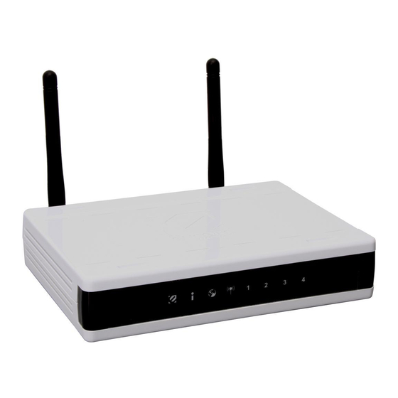
HARDWARE INSTALLATION Front Panel The figure below shows the front panel of ENCORE 802.11n Wireless Router. SYSTEM (i icon) This indicator blinking green means the WLAN Router is working successfully. Otherwise, this indicator always on or off means the function of the WLAN Router has failed. -
Page 12: Rear Panel
Rear Panel The figure below shows the rear panel of ENCORE 802.11n Wireless Router. Antenna There is two 2dBi gain antennas on the rear panel for wireless connection. LAN (1-4) Four RJ-45 10/100Mbps Auto-MDIX ports for connecting to either 10Mbps or 100Mbps Ethernet connections. -
Page 13: Hardware Connections
LAN port of the WLAN Router. Since ENCORE 802.11n Wireless Router has four ports, you can connect up to four computers directly to the unit. Then you do not have to buy a switch to connect these computers since one WLAN Router functions both as a connection-sharing unit and as a switch. -
Page 14: Pc Network Tcp/Ip Setting
PC NETWORK TCP/IP SETTING The network TCP/IP settings differ based on the computer’s operating system (Win95/98/ME/NT/2000/XP) and are as follows. Windows 95/98/ME 1. Click on the “Network neighborhood” icon found on the desktop. 2. Click the right mouse button and a context menu will be show. 3. -
Page 15: Windows 2000
6. Select “None” for the “Gateway address” field. Windows 2000 Double click on the “My Computer” icon on the desktop. When “My Computer” window opens, open the “Control Panel” and then open the “Network dialup connection” applet. Double click on the “Local area network connection” icon. Select “Properties”... -
Page 16: Windows Xp
Windows XP Point the cursor and click the right button on the “My Network Place” icon. Select “properties” to enter the TCP/IP setting window. 1. Set “IP address” to “Obtain an IP address automatically.” 2. Set “DNS” to “Obtain DNS server address automatically.” - 10 -... -
Page 17: Configuration
CONFIGURATION First make sure that the network connections are functioning normally. This WLAN Router can be configured using Internet Explorer 5.0 or newer web browser versions. Login to the WLAN Router through Wireless LAN Before configuring the WLAN Router through WLAN, make sure that the SSID, Channel and the WEP is set properly. -
Page 18: Setup Wizard
Setup Wizard Setup wizard is provided as part of the web configuration utility. User can simply follow the step-by-step process to get the wireless Router configuration ready to run in 6 easy steps by clicking on` the “Wizard” button on the function menu. The following screen will appear. - Page 19 Step 2: Choose time zone Select the time zone from the drop down list. Please click “Next” to continue. Step 3: Set LAN connection and DHCP server Set user’s IP address and mask. The default IP is 192.168.1.1. If the user chooses to enable DHCP, please click “Enable”.
- Page 20 Obtain IP automatically (DHCP client): If the user has enabled DHCP server, choose "Obtain IP automatically (DHCP client)" to have the WLAN Router assign IP addresses automatically. - 14 -...
- Page 21 Fixed IP Address: If the Internet Service Provider (ISP) assigns a fixed IP address, choose this option and enter the assigned WAN IP Address, WAN Subnet Mask, WAN Gateway Address and DNS Server Addresses for the WLAN Router. - 15 -...
- Page 22 PPPOE PPPoE to obtain IP automatically: If connected to the Internet using a PPPoE (Dial-up xDSL) connection, and the ISP provides a User Name and Password, then choose this option and enter the required information. - 16 -...
- Page 23 PPPoE with a Specify IP address: If connected to the Internet using a PPPoE (Dial-up xDSL) connection, and the ISP provides a User Name, Password and a Fixed IP Address, choose this option and enter the required information. - 17 -...
- Page 24 PPTP: If connected to the Internet using a PPTP xDSL connection, enter your IP, Subnet Mask, Gateway, Server IP, PPTP Account and PPTP Password. - 18 -...
- Page 25 L2TP: If connected to the Internet using a L2TP (Dial-up xDSL) connection and the ISP provides a Server IP, Account and Password information, choose this option and enter the required information. - 19 -...
- Page 26 Big Pond Cable(Australia): If your ISP is Big Pond Cable, the ISP will provide a User Name, Password, Authentication Server and Login Server IP (Optional). Choose this option and enter the required information. - 20 -...
- Page 27 Step 5: Set Wireless LAN connection Click “Enable” to enable Wireless LAN. If user enables the Wireless LAN, type the SSID in the text box and select a communications channel. The SSID and channel must be the same as wireless devices attempting to connect to the WLAN Router. (When in FCC domain, you could chose ch1~ch11;...
-
Page 28: Wan Setting
WAN Setting This function enables users to set up the WLAN Router WAN connection, specify the IP address for the WAN, add DNS numbers, and enter the MAC address. Connection Type: Select the connection type, either DHCP client, Fixed IP or PPPoE, PPTP, L2TP or BigPond from the drop-down list. -
Page 29: Pppoe With Obtain Ip Automatically
Clone MAC Address: If your ISP requires you to enter a specific MAC address, please enter it in. The Clone MAC Address button is used to copy the MAC address of your Ethernet adapter to the Router. PPPoE with Obtain IP Automatically If connected to the Internet using a PPPoE (Dial-up xDSL) Modem, the ISP will provide a Password and User Name, and then the ISP uses PPPoE. -
Page 30: Pppoe With Specify Ip
PPPoE with Specify IP If connected to the Internet using a PPPoE (Dial-up xDSL) Modem, the ISP will provide a Password, User Name and a Specify IP Address, choose this option and enter the required information. - 24 -... -
Page 31: Pptp/L2Tp With Obtain Ip Automatically
PPTP/L2TP with Obtain IP Automatically If connected to the Internet using a PPTP/L2TP (Dial-up xDSL) connection, enter the your Server IP, PPTP/L2TP Account and PPTP/L2TP Password, if your ISP has provided you with a DNS IP address, enter it in the DNS field, otherwise, leave it zero. -
Page 32: Bigpond Cable
BigPond Cable If your ISP is Big Pond Cable, the ISP will provide a User Name, Password, Authentication Server and Login Server IP (Optional). Choose this option and enter the required information. Dynamic DNS: This synchronizes the DDNS server with your current Public IP address when you are online. -
Page 33: Wireless Setting
Wireless setting This section enables user to set wireless communications parameters for the router's wireless LAN feature. Basic This page allow user to enable and disable the wireless LAN function, create a SSID, and select the channel for wireless communications. Enable/Disable: Enables or disables wireless LAN via the WLAN Router. -
Page 34: Security
SSID Broadcast: While SSID Broadcast is enabled, all wireless clients will be able to view the WLAN Router’s SSID. For security purposes, users may want to disable SSID Broadcast to ensure only authorized clients have access. Security This function enables user to set authentication type for secure wireless communications. - Page 35 WEP: Open System and Shared Key requires the user to set a WEP key to exchange data with other wireless clients that have the same WEP key. WEP Key Format: Select the key format from the drop-down list HEX or ASCII. WEP Key Length: Select the level of encryption from the drop-down list.
- Page 36 Cipher Type: Select the cipher type for TKIP or AES encryption, Selected Auto for auto detects the cipher type. RASIUS Server: 1. Enter the IP address, Port used and Shared Secret by the Primary Radius Server. 2. Enter the IP address, Port used and Shared Secret by the Secondary Radius Server.
-
Page 37: Advanced
Advanced This function enables user to configure advanced wireless functions. Wi-Fi Protected Setup This screen enables users to configure the Wi-Fi Protected Setup function. WPS: Enable or Disable the WPS (Wi-Fi Protected Setup) function Status: Display the state (Un-configured State/Configured State) information of WPS. - Page 38 Push Button Configuration: Clicking this button will invoke the Push Button Configuration (PBC) method of WPS. It is only used when WLAN Router acts as a Registrar. - 32 -...
-
Page 39: Lan Setting
LAN Setting The function enables user to configure the LAN port IP address & DHCP Server. Basic This page leads to set LAN port properties, such as the host name, IP address, and subnet mask. Host Name: Type the host name in the text box. The host name is required by some ISPs. -
Page 40: Dhcp
DHCP DHCP Server: Enables the DHCP server to allow the router to automatically assign IP addresses to devices connecting to the LAN. DHCP is enabled by default. DHCP Server Start IP: Type an IP address to serve as the start of the IP range that DHCP will use to assign IP addresses to all LAN devices connected to the router. -
Page 41: Access Control Setting
Access Control Setting This access control enables you to define access restrictions, set up protocol and IP filters, create virtual servers, define access for special applications such as games, and set firewall rules. Filter Using filter to deny or allow the users to access. Five types of filters to select: MAC, IP Filter, URL blocking, Domain blocking and Protocol filter. - Page 42 MAC Address: Type the MAC address of the user's network interface. Add: Click to add the user to the list at the bottom of the page. Update: Click to update information for the user, if you have changed any of the fields.
- Page 43 Protocol/IP Filters This protocol filter enables you to allow and deny access based upon a communications protocol list you create. The protocol filter profiles are listed in the table at the bottom of the page. Note: When selecting items in the table at the bottom, click anywhere in the item. The line is selected, and the fields automatically load the item's parameters, which you can edit.
-
Page 44: Virtual Server
Cancel: Click the Cancel button to erase all fields and enter new information. Virtual Server This screen enables users to create a virtual server via the WLAN Router. If the WLAN Router is set as a virtual server, remote users requesting Web or FTP services through the WAN are directed to local servers in the LAN. -
Page 45: Special Ap
Delete: Select a listed item and click “Delete” to remove the item from the list. Cancel: Click Cancel button to erase all fields and enter new information. Special AP This screen enables users to specify special applications, such as games which require multiple connections that are blocked by NAT. -
Page 46: Dmz
Incoming: Defines which incoming communications users are permitted to connect with. ● Protocol: Select the protocol (TCP, UDP, or ICMP) that can be used by the incoming communication. ● Port: Type the port number that can be used for the incoming communication. -
Page 47: Firewall Settings
Firewall settings - 41 -... -
Page 48: System Setting
System Setting This system setting enables users to change password, set the device time, view the device information, restart the system, save and load different settings as profiles, restore factory default settings, upgrade the firmware, and ping remote IP addresses….etc. Password This function enables users to set administrative and user passwords. -
Page 49: Time
Time This function enables users to set the time and date for the WLAN Router's real- time clock, select properly time zone, and enable or disable daylight saving. Local Time: Displays the local time and date. Time Zone: Select the time zone from the drop-down list. Synchronize the clock with NTP Server: Enable or disable the WLAN Router automatically adjust the system time from NTP Server. -
Page 50: Device Information
Device Information This function enables users to view the WLAN Router’s WAN, Wireless, LAN and System configurations. WAN: This section displays the WAN interface configuration including the MAC address, Connection status, DHCP client status, IP address, Subnet mask, Default gateway, and DNS. Wireless: This section displays the wireless configuration information, including the MAC address, the Connection status, SSID, Channel and Authentication type. -
Page 51: Log
This function enables users to view a running log of Router system statistics, events, and activities. The log displays up to 200 entries. Older entries are overwritten by new entries. The Log screen commands are as follows: Click “First Page” to view the first page of the log Click “Last Page”... -
Page 52: Log Setting
Log Setting This function enables users to set Router Log parameters. SMTP Server: Type your SMTP server address here. Send to: Type an email address for the log to be sent to. Click “Email Log Now” to immediately send the current log. SMTP Authentication: Selected the Enabled if the SMTP server need for authentication, fill in account name and password in SMTP Account field and SMTP Password field. - Page 53 Dropped Packets: Displays information about packets that have not been transferred successfully. Notice: Displays important notices by the system administrator. - 47 -...
-
Page 54: Statistic
Statistic This function displays a table that shows the rate of packet transmission via the WLAN Router’s LAN, WAN and Wireless ports (in bytes per second). Click “Reset” to erase all statistics and begin logging statistics again. Restart Click “Restart” to restart the system in the event the system is not performing correctly. -
Page 55: Firmware
Firmware This function enables users to keep the WLAN Router firmware up to date. Please follow the below instructions: Download the latest firmware from the manufacturer's Web site, and save it to disk. Click “Browse” and go to the location of the downloaded firmware file. Select the file and click “Upgrade”... -
Page 56: Configuration
Configuration This function enables users to save settings as a profile and load profiles for different circumstances. User can also load the factory default settings, and run a setup wizard to configure the WLAN Router and Router interface. - 50 -... -
Page 57: Upnp
UPnP This function enables users to enable or disable the UPnP function on the WLAN Router. UPnP: Select to enable or disable the UPnP function on the WLAN Router. - 51 -... -
Page 58: Ping Test
Ping Test The ping test enables users to determine whether an IP address or host is present on the Internet. Type the host name or IP address in the text box and click Ping button to start the Ping test. - 52 -... -
Page 59: Remote Management
Remote Management This function enables users to set up remote management. Using remote management, the WLAN Router can be configured through the WAN via a Web browser. A user name and password are required to perform remote management. HTTP: Enables users to set up HTTP access for remote management. Remote IP Range: Type a range of IP addresses that can be pinged from remote locations Gaming mode: If user is experiencing difficulties when playing online games or... -
Page 60: Technical Specifications
TECHNICAL SPECIFICATIONS General Standards IEEE 802.3u 100BASE-TX Fast Ethernet IEEE 802.11n draft 2.0; IEEE 802.11g; IEEE 802.11b Protocol CSMA/CD Radio Technology DSSS/OFDM Data Transfer 802.11n mode: up to 300Mbps (auto sense) Rate 802.11g mode: up to 54Mbps (auto sense) 802.11b mode: up to 11Mbps (auto sense) Ethernet: 10Mbps (half duplex), 20Mbps (full-duplex) Fast Ethernet: 100Mbps (half duplex), 200Mbps (full- duplex) Receiver... -
Page 61: Faq
Q: What can I do if I forgot my password, or my router is not working correctly? A: Step 1 Locate the reset pinhole on the back of the unit. Step 2 With the unit powered on, press and hold the Reset button. Step 3 Hold the Reset button for about 15 seconds. - Page 62 ELN/username@earthlink.net and your password, where username is your own username (some Earthlink users may not need the ELN/ in front of username). For SBC Global users, enter username@sbcglobal.net. For Ameritech users, enter username@ameritech.net. For BellSouth users, enter username@bellsouth.net.** For most other ISPs, enter username. Step 7 Idle Time Out should be set to zero.
Need help?
Do you have a question about the ENHWI-N2 and is the answer not in the manual?
Questions and answers