Table of Contents
Advertisement
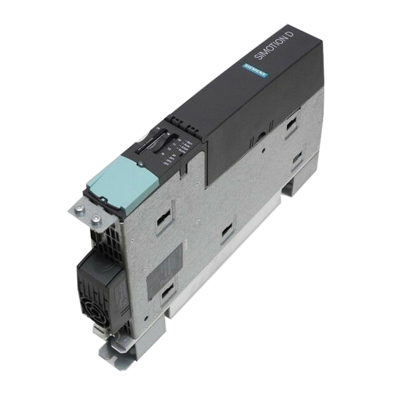
SIMOTION D4x5
SIMOTION
SIMOTION D4x5
Manual
Valid for SIMOTION D425, D435, D445 and D445-1
as well as CX32, CBE30 and TB30
02/2012
___________________
Preface
___________________
Description
___________________
Operator control (hardware)
___________________
Interfaces
___________________
Technical data
___________________
Dimension drawings
Supplementary system
___________________
components
___________________
Available spare parts and
accessories
___________________
Standards and approvals
___________________
ESD guidelines
1
2
3
4
5
6
7
A
B
Advertisement
Table of Contents

Related Manuals for Siemens SIMOTION CX32


Summarization of Contents
SIMOTION D4x5 Manual Overview
Preface
Introduces the manual and its content.
Description
Provides an overview of the SIMOTION D4x5 system.
Operator Control (Hardware)
Details the physical operator control elements and displays.
Interfaces
Describes the various hardware interfaces available on the unit.
Technical Data
Lists the technical specifications and data for the device.
Dimension Drawings
Provides physical dimensions and mounting information.
Supplementary System Components
Covers additional modules that can be used with the system.
Available Spare Parts and Accessories
Lists orderable spare parts and accessories for the product.
Standards and Approvals
Details compliance with relevant industry standards and certifications.
ESD Guidelines
Provides instructions for handling electrostatic sensitive devices.
Legal Information and Safety
Warning Notice System
Explains the warning symbols and their meanings for safety.
Qualified Personnel Requirements
Defines the necessary qualifications for operating the product.
Proper Use of Siemens Products
Guidelines for the correct application and handling of Siemens products.
Trademarks and Disclaimer of Liability
Lists trademarks and the document's liability disclaimer.
Preface Details and Scope
Scope of Manual Applicability
Defines the applicability of this manual to specific device versions.
Standards Compliance Statement
States compliance with ISO 9001 quality guidelines.
Content of the Manual Sections
Lists the main sections within the manual and their purpose.
Preface Additional Information and Support
SIMOTION Documentation Overview
Provides an overview of the SIMOTION documentation package.
Support and Contact Information
Lists hotline, internet addresses, and contact for documentation feedback.
Preface Further Resources
Training and FAQs
Information on training courses and frequently asked questions.
Technical Support and Disposal Guidelines
Contact info for technical support and guidelines for product disposal.
Description: System Overview
SIMOTION D System Introduction
Introduces SIMOTION D as a drive-based version of SIMOTION.
SIMOTION D4x5 Control Unit
Details the D4x5 as a multi-axis Control Unit in SINAMICS S120 format.
Description: System Overview Details
SIMOTION D4x5 Application Suitability
Lists typical applications where SIMOTION D4x5 is ideal.
SIMOTION D4x5 Performance Variants
Compares D425, D435, D445/D445-1 based on performance and axes.
Description: Hardware Components
SIMOTION D4x5 Hardware Architecture
Explains the D4x5 as a Control Unit with SINAMICS Integrated drive.
Description: System Components
SIMOTION D Axis Grouping Elements
Lists the core elements of a SIMOTION D axis grouping.
Drive Computing Performance Extension
Methods to expand the computing performance of the D4x5.
SIMOTION D Software Components
Details the software components on the CompactFlash card.
Description: System Components and Interfaces
Central Components and Interfaces
Lists interfaces (PROFIBUS DP, Ethernet, PROFINET IO, DRIVE-CLiQ).
Description: PROFIBUS DP System Integration
PROFIBUS DP Connectable Devices
Lists devices that can communicate via PROFIBUS DP.
Description: Network Interfaces
Ethernet Interface Communication
Details communication capabilities via Ethernet interfaces.
PROFINET IO Communication
Explains PROFINET IO communication using CBE30.
Description: DRIVE-CLiQ Topology
DRIVE-CLiQ Interface Advantages
Lists the benefits of using the DRIVE-CLiQ topology.
DRIVE-CLiQ Connected Components
Lists components that can communicate via DRIVE-CLiQ.
Description: Optional System Expansion
Optional Components for D4x5
Describes optional boards like CBE30 and TB30 for expansion.
Description: I/O Integration
I/O Module Compatibility and Integration
Notes on approved I/O modules and integration requirements.
Description: SIMOTION D425/D435 Representation
D425/D435 Interfaces and Front Panel
Shows the location of interfaces and front panel elements.
Description: SIMOTION D445 Representation
D445 Interfaces and Front Panel
Illustrates interfaces and front panel elements of the D445.
D445 Fan/Battery Module Requirement
CAUTION regarding the necessity of a fan/battery module for D445.
Description: SIMOTION D445-1 Representation
D445-1 Interfaces and Front Panel
Shows interfaces and front panel elements of the D445-1.
Description: SIMOTION D445-1 Operation
D445-1 Fan/Battery Module Requirement
CAUTION regarding the necessity of a double fan/battery module for D445-1.
Description: Nameplates
Side-Mounted Type Plate Information
Details information found on the unit's side type plate.
Description: MAC Addresses
Ethernet Interface MAC Address Plate
Location and visibility of the MAC address plate on the front.
Description: Safety Notes
Operational Safety Precautions
Important notices and cautions for safe operation and installation.
Description: CompactFlash Card Usage
1.9.1 CompactFlash Card Usage and Function
Describes the insertion and function of the CompactFlash card.
Description: CompactFlash Card Properties
CF Card Mandatory Operation and Use
Explains the necessity of the CF card and its uses.
Additional CF Card Information
Refers to other manuals for detailed CF card operations.
Description: CompactFlash Card Details
1.9.2 CompactFlash Card Type Plate
Information presented on the CompactFlash Card type plate.
Pre-installed Runtime Licenses
Explains how runtime licenses are indicated on the CF card.
Description: CompactFlash Card Licenses
Available Z Options and Licenses
Lists various software options and licenses for CF cards.
Description: Data Matrix Code on CF Card
1.9.3 Data Matrix Code Analysis
Analysis of the machine-readable identification via 2D code.
Operator Control (Hardware)
2.1 Overview of Operator Controls
Shows the arrangement of operator control and display elements.
Operator Control (Hardware) Details
D425/D435/D445 Operator Controls
Illustrates operator controls and display elements on D425/D435/D445.
D445-1 Operator Controls
Illustrates operator controls and display elements on D445-1.
Operator Control Elements
2.2 Operator Control Elements
Details the operator control elements on the unit.
Service and Mode Selector Switch
Explains the function of the service and operation mode selector switches.
Operator Control: Mode Selector Switch
Mode Selector Switch Functionality
Describes mode selector positions and their meanings.
Operator Control: Mode Selector States
Mode Selector Switch States
Explains the operating states (RUN, STOPU, STOP, MRES) set by the switch.
Recommended Mode Selection Method
Recommends using SIMOTION SCOUT for mode switching.
Operator Control: Service Selector Switch
Service Selector Switch Positions
Details the switch positions for service and data management.
Additional References for Operation
Lists further documentation for operating modes and upgrades.
Operator Control: Reset and Display Elements
2.2.2 RESET Button Operation
Describes the location and function of the RESET button.
2.3 LED and 7-Segment Display Arrangement
Shows the layout of LEDs and the 7-segment display.
Operator Control: Display Meanings
LED Display Meanings
Explains the meaning of each LED status indicator.
7-Segment Display Status Information
Describes the information provided by the 7-segment display.
Interfaces Overview
3.1 Interface Overview
Lists all available and non-usable interfaces on the SIMOTION D4x5.
Interfaces: DRIVE-CLiQ
3.2 DRIVE-CLiQ Interface Description
Explains the DRIVE-CLiQ interface and its properties.
DRIVE-CLiQ Connector Position
Shows the physical location of the DRIVE-CLiQ connectors.
Interfaces: DRIVE-CLiQ Details
DRIVE-CLiQ Interface Characteristics
Lists characteristics like connector type and max cable length.
DRIVE-CLiQ Pin Assignment
Details the pinout for DRIVE-CLiQ interfaces.
Interfaces: Ethernet
3.3 Ethernet Interface Functions
Describes the functions and capabilities of Ethernet interfaces.
Ethernet Connector Position
Shows the physical location of Ethernet connectors.
Interfaces: Ethernet Details
Ethernet Interface Features
Lists features like connector type, cable type, and length.
Ethernet Pin Assignment and Cabling
Explains pin assignments and cable requirements for Ethernet.
Interfaces: Digital I/O
3.4.1 Digital I/O Interface Features
Details features of digital I/O connectors X122 and X132.
Digital I/O Connector Positions
Shows the physical location of digital I/O connectors.
Interfaces: Digital I/O Wiring
SIMOTION D4x5 Digital I/O Wiring Diagram
Provides the wiring and block diagram for digital inputs/outputs.
Interfaces: Digital I/O Assignments
X122 Interface Assignment
Details the pin assignments for digital inputs/outputs on X122.
X132 Interface Assignment
Details the pin assignments for digital inputs/outputs on X132.
Interfaces: Using Digital I/O
Connecting Sensors and Actuators to Digital I/O
How to connect sensors and actuators to digital I/O.
Digital Inputs Functionality
Describes the capabilities of the unit's 8 digital inputs.
Interfaces: Bidirectional Digital I/O
Bidirectional Digital I/O Usage
Explains the use of bidirectional digital inputs/outputs.
Additional References for Digital I/O
Refers to other manuals for detailed I/O configuration.
Interfaces: Power Supply
3.5 Power Supply Interface
Details the interface for external 24 V power supply connection.
Power Supply Interface Assignments
Explains the pin assignments for the power supply connector.
Interfaces: PROFIBUS DP
3.6 PROFIBUS DP Interface Features
Lists features of the PROFIBUS DP interfaces (X126, X136).
PROFIBUS DP Interface Assignment (X126)
Details the pin assignments for the PROFIBUS DP1 interface (X126).
Interfaces: PROFIBUS DP Details
PROFIBUS DP Interface Assignment (X136)
Details the pin assignments for the PROFIBUS DP2/MPI interface (X136).
PROFIBUS Connector Positions
Shows the physical location of the PROFIBUS connectors.
Interfaces: PROFIBUS DP Connectivity
Connectable Devices via PROFIBUS DP
Lists devices that can be connected to PROFIBUS DP interfaces.
Interfaces: Slot and Measuring Sockets
3.7 CompactFlash Card Slot
Describes the 50-pin connector for the SIMOTION CF card.
3.8 Measuring Sockets Application
Explains the use of measuring sockets for analog signal output.
Interfaces: USB and Option Slot
3.9 USB Interface Functionality
Details the USB interfaces for upgrading the device.
3.10 Option Slot Options
Lists plug-in options like TB30 and CBE30 for the option slot.
Technical Data: Memory
4.1 Technical Data D4x5: System Memory
Details memory sizes for diagnostics buffer, RAM, and RAM disk.
CompactFlash Card Specifications
Lists memory capacity and weight for CompactFlash cards.
Technical Data: CF Card Limitations
CompactFlash Card Runtime Limitations
Explains limitations when using CF cards with SIMOTION runtime.
D4x5 Dimensions and Weight
Provides dimensions and weight for D425/D435, D445, and D445-1.
Technical Data: Environmental Conditions
D4x5 Ambient Conditions Requirements
Specifies permissible ambient temperature, humidity, and altitude.
Backup Battery Handling and Storage
Information on shipping, storage, and handling of backup batteries.
Technical Data: Performance
PLC and Motion Control Performance
Compares maximum axes and cycle clocks for D4x5 variants.
Integrated Drive Control Capabilities
Details the number of axes for integrated drive control.
Technical Data: Communication Interfaces
Interface Communication Capabilities
Summarizes communication capabilities via DRIVE-CLiQ, Ethernet, PROFIBUS, PROFINET.
Address Space Allocation
Details logical and physical I/O address space for interfaces.
Technical Data: General and Digital Inputs
General Technical Data (Fan, Power Supply)
General data on fans, power supply, and current consumption.
Digital Input Specifications
Details input voltage, isolation, and delay for digital inputs.
Technical Data: Digital I/Os
Digital I/Os (Parameterizable)
Specifies parameters for digital inputs/outputs used as inputs or outputs.
Technical Data: Non-Volatile Data Backup
Non-Volatile Data Backup Details
Information on backup time, charging, approvals, and markings.
Technical Data: Real-Time Clock
4.2 Clock Features
Lists properties and functions of the integrated real-time clock.
Real-Time Clock Operation (Power OFF)
Explains clock behavior when the device is powered off.
Technical Data: Power Supply
4.3 D4x5 Power Supply Specifications
Details input voltage, current consumption, and maximum current.
Power Supply Undervoltage Detection
Explains how undervoltage is detected and handled.
Technical Data: Protection Class
4.4 Protection Class and Degree of Protection
Specifies safety class and protection against foreign bodies/water.
Technical Data: Input/Output Circuit
4.5 Input and Output Circuitry
Shows the protective circuits for input and output stages.
Dimension Drawings
5.1 Dimension Drawing D425/D435
Provides dimensional drawings for D425 and D435 models.
D425/D435 Installation Clearance Notice
NOTICE regarding required installation clearances for D425/D435.
Dimension Drawings: D445
5.2 Dimension Drawing D445
Provides dimensional drawings for the D445 model.
D445 Operation with Fan/Battery Module
NOTICE about the mandatory fan/battery module for D445.
Dimension Drawings: D445-1
5.3 Dimension Drawing D445-1
Provides dimensional drawings for the D445-1 model.
D445-1 Operation with Double Fan/Battery Module
NOTICE about the mandatory double fan/battery module for D445-1.
Dimension Drawings: CAD and Circuit Macros
CAD Data and Dimension Drawings
Information on generating 2D/3D CAD data using CAD CREATOR.
EPLAN Circuit-Diagram Macros
Availability of EPLAN macros for circuit diagram creation.
Supplementary System Components
6.1 Supplemental System Components Overview
Shows how supplementary components connect to the D4x5.
Supplementary System Components: Fan/Battery Module
6.2 Fan/Battery Module Functions
Details tasks of the fan/battery module (cooling, data buffering).
SIMOTION D4x5 Cooling Requirements
Explains when an external fan/battery module is required for cooling.
Supplementary System Components: Fan/Battery Module Details
Fan/Battery Module Permissible Temperatures
Specifies maximum permissible supply air temperatures.
Fan Control and Failure Indication
Describes fan control logic and failure indicators.
Supplementary System Components: Data Buffering
Buffering Data with SuperCap and CF Card
Explains data buffering using SuperCap and options for longer retention.
Fan/Battery Module Battery Information
Details the 3 V lithium battery used in the module.
Supplementary System Components: Installing Fan/Battery Module
6.2.2 Installing the Fan/Battery Module
Step-by-step procedure for installing the fan/battery module.
Supplementary System Components: Replacing Fan/Battery Module Battery
6.2.3 Replacing the Fan/Battery Module Battery
Step-by-step procedure for replacing the battery in the module.
Supplementary System Components: Backup Battery Safety
Rules for Handling Backup Batteries
DANGER notice and rules for safe handling of backup batteries.
Battery Replacement Recommendation
Recommends timely battery replacement to prevent data loss.
Supplementary System Components: TB30 Terminal Board
6.3 TB30 Terminal Board Description
Describes the TB30 as a terminal expansion module.
TB30 Safety Information
CAUTIONS regarding terminal board insertion/removal and installation.
Supplementary System Components: TB30 Interfaces
6.3.3 Interfaces Overview
Shows the arrangement of interfaces on the front of the TB30.
Supplementary System Components: TB30 Connection Diagram
6.3.3.2 TB30 Connection Diagram
Schematic diagram showing TB30 connections for inputs/outputs and power.
Supplementary System Components: TB30 Power Supply
6.3.3.3 Power Supply of Digital Outputs
Details the terminal block X424 for digital output power supply.
X424 Wiring Features
Specifies wiring characteristics for the X424 connector.
Supplementary System Components: TB30 Digital I/O
6.3.3.4 Digital Inputs/Outputs (X481)
Details the terminal block X481 for digital inputs/outputs.
TB30 Digital I/O Notes
Notes on open input interpretation and 24 V supply interruptions.
Supplementary System Components: TB30 Wiring
X481 Wiring Characteristics
Specifies wiring characteristics for the X481 connector.
Supplementary System Components: TB30 Analog I/O
6.3.3.5 Analog Inputs and Outputs (X482)
Details the terminal block X482 for analog inputs/outputs.
TB30 Analog I/O CAUTION
CAUTION regarding common-mode range and offset voltage.
Supplementary System Components: TB30 Technical Data
Working with Analog Inputs
References for working with analog inputs.
TB30 Commissioning Information
Points to manual for commissioning procedures.
TB30 Technical Specifications Summary
Summarizes electronic power supply, response time, dimensions, and weight.
Supplementary System Components: Controller Extension CX32
6.4 Controller Extension CX32 Overview
Introduces the CX32 module and its scaling capabilities.
CX32 Drive Quantity Structures
Quantifies drive limits based on CX32 usage with SIMOTION D435/D445.
Supplementary System Components: CX32 Drive Control
CX32 Drive Quantity Structures (V4.0 HF2)
Quantifies drive limits for V4.0 HF2 based on CX32 usage.
CX32 Mixed Drive Operation Notes
Notes on mixed operation of servo, vector, and V/f controlled drives on CX32.
Supplementary System Components: CX32 Interfaces
6.4.2 CX32 Interface Positioning
Shows the physical location of interfaces on the CX32.
CX32 Installation Clearance CAUTION
CAUTION regarding installation clearances for the CX32.
Supplementary System Components: CX32 Interface List
6.4.2.1 CX32 List of Interfaces
Lists the available and non-usable interfaces on the CX32.
Supplementary System Components: CX32 DRIVE-CLiQ and Digital I/O
6.4.2.2 CX32 DRIVE-CLiQ Interface Details
Details the DRIVE-CLiQ interface characteristics for CX32.
6.4.2.3 CX32 Digital Inputs/Outputs (X122) Interface Characteristics
Specifies wiring characteristics for the CX32 X122 connector.
Supplementary System Components: CX32 Digital I/O Wiring
CX32 Digital I/O Connector Positioning
Shows the location of the X122 digital I/O connector.
CX32 Digital I/O Connection and Block Diagram
Provides the connection and block diagram for CX32 digital I/Os.
Supplementary System Components: CX32 Digital I/O Assignments
CX32 X122 Interface Assignment
Details the pin assignments for the CX32 X122 connector.
Using CX32 Digital Inputs/Outputs
Explains how to connect sensors and actuators to CX32 digital I/Os.
Supplementary System Components: CX32 Digital I/O Usage
CX32 Digital Input Functionality
Describes the capabilities of the CX32's 4 digital inputs.
CX32 Bidirectional Digital I/O Usage
Explains the use of the CX32's 4 bidirectional digital inputs/outputs.
Supplementary System Components: CX32 Power Supply
6.4.2.4 CX32 Power Supply Application
Details the interface for external power supply connection to CX32.
CX32 Power Supply Interface Assignments
Explains the pin assignments for the CX32 power supply connector.
Supplementary System Components: CX32 Measuring Sockets and LEDs
6.4.2.5 CX32 Measuring Sockets Application
Explains the use of CX32 measuring sockets for analog signals.
6.4.3 CX32 LED Displays Description
Describes the meaning of the RDY and DP1 LEDs on the CX32.
6.4.4 CX32 RESET Button Function
Refers to manual for function of the CX32 RESET button.
Supplementary System Components: CX32 Commissioning and Technical Data
CX32 Commissioning Information
Points to manual for CX32 commissioning procedures.
CX32 Technical Data Summary
Summarizes CX32 diagnostics buffer, dimensions, and weight.
Supplementary System Components: CX32 Environmental and Communication
CX32 Environmental Requirements
Specifies ambient conditions, pollution degree, and protection for CX32.
CX32 Integrated Drive Control and Communication
Details integrated drive control and interface communication for CX32.
Supplementary System Components: CX32 General Data
CX32 General Technical Data
Lists power supply, current consumption, and power loss for CX32.
CX32 Digital Input Specifications
Details digital input voltage, isolation, and delay for CX32.
Supplementary System Components: CX32 Digital I/O
CX32 Digital I/Os (Parameterizable)
Specifies parameters for CX32 digital inputs/outputs.
Supplementary System Components: CBE30 Ethernet
6.5 CBE30 Communication Board Features
Details the features of the CBE30 Ethernet communication board.
CBE30 Installation CAUTION
CAUTION regarding insertion/removal of the CBE30 board.
Supplementary System Components: CBE30 Details
CBE30 View and LED Displays
Shows the front view of CBE30 with connections and LEDs.
CBE30 Type Plate Information
Information found on the CBE30 type plate.
Supplementary System Components: CBE30 MAC Address and Safety
CBE30 MAC Address Information
Location and use of the MAC address plate on the CBE30.
CBE30 Safety Information
CAUTIONS regarding CBE30 insertion/removal and installation.
Supplementary System Components: CBE30 Ethernet Interfaces
6.5.4.1 CBE30 Ethernet Interface Features
Details features of the X1400 Ethernet interface on CBE30.
CBE30 Ethernet Pin Assignment
Explains the pin assignments for the X1400 Ethernet interface.
Supplementary System Components: CBE30 Port and LED Displays
CBE30 Port Positioning
Shows the location of the four ports on the CBE30.
CBE30 LED Display Meanings
Explains the meaning of link, activity, sync, and fault LEDs.
Supplementary System Components: CBE30 Dimension Drawing
6.5.5 CBE30 Dimension Drawing
Provides dimensional drawings for the CBE30 communication board.
Supplementary System Components: CBE30 Commissioning and Technical Data
CBE30 Commissioning References
Lists manuals for CBE30 commissioning.
CBE30 Technical Data Summary
Lists current requirement, approvals, environmental conditions, and dimensions.
Supplementary System Components: Terminal Module TM31
6.6 TM31 Terminal Module Features
Describes the TM31 module for expanding digital/analog I/O.
TM31 Interface Overview
Lists the types and quantities of terminals on the TM31.
TM31 Installation Clearance CAUTION
CAUTION regarding installation clearances for the TM31.
Supplementary System Components: Terminal Module TM41
6.7 TM41 Terminal Module Features
Describes the TM41 module for expanding I/O and TTL encoder output.
TM41 Interface Overview
Lists the types and quantities of terminals on the TM41.
TM41 Installation Clearance CAUTION
CAUTION regarding installation clearances for the TM41.
Supplementary System Components: Terminal Module TM54F
6.8 TM54F Terminal Module Features
Describes the TM54F for safe digital I/O for Safety Integrated functions.
TM54F Interface Overview
Lists types and quantities of terminals on the TM54F.
TM54F Installation Clearance CAUTION
CAUTION regarding installation clearances for the TM54F.
Supplementary System Components: Terminal Modules TM15/TM17 High Feature
6.9 TM15/TM17 High Feature Terminal Module Features
Describes TM15/TM17 for measuring inputs/outputs, drive-related I/O.
TM15 and TM15 DI/DO Details
Details parameterization of TM15 DI/DO channels.
TM17 High Feature Functionality
Highlights TM17 High Feature's higher resolution, accuracy, and filter.
Supplementary System Components: CUA31/CUA32 Control Unit Adapter
6.10 CUA31/CUA32 Adapter Features
Describes connecting power modules via DRIVE-CLiQ using CUA31/CUA32.
CUA31/CUA32 Interface Summary
Lists the number of interfaces on CUA31 and CUA32 adapter modules.
CUA31/CUA32 Installation Clearance CAUTION
CAUTION regarding installation clearances and ventilation openings.
Supplementary System Components: DMC20 DRIVE-CLiQ Hub
6.11 DMC20 DRIVE-CLiQ Hub Features
Describes DMC20/DME20 hubs for DRIVE-CLiQ line distribution.
Available Spare Parts and Accessories
Spare Parts and Accessories for SIMOTION D4x5
Lists order numbers for spare parts and accessories.
Available Spare Parts and Accessories Information
Ordering Data for SINAMICS Components
Refers to PM 21 Catalog for SINAMICS component ordering data.
Spares On Web Information System
Information on accessing spare parts availability via Spares On Web.
Standards and Approvals
A.1 General Rules: CE Marking
States compliance with EC Directives and harmonized European standards.
A.1 General Rules: Electromagnetic Compatibility
EMC compliance based on DIN EN 61800-3, Category C2.
A.1 General Rules: cULus Approval
Lists UL component marks and file numbers for US and Canada.
A.1 General Rules: EMC Regulations (USA)
FCC statement on compliance for Class A digital devices.
Standards and Approvals: General Rules Details
USA: Modifications and Operations Conditions
FCC rules on modifications and operational conditions.
Canada: Compliance Notice
Canadian ICES-003 compliance statement for digital apparatus.
South Korea: EMC Limit Values
EMC limits for Korea and necessary additional measures.
Declaration of Conformity Information
Provides link to the online Declaration of Conformity.
Standards and Approvals: Device-Specific Notes
General Warning Information: Hazardous Areas
CAUTION about risks in hazardous areas when disconnecting connections.
Australia: C-Tick Marking
Compliance with AS/NZS CISPR 22 requirements.
Note Regarding SIMOTION D EMC Requirements
Explains EN 61800-3 EMC requirements for variable speed drive systems.
Standards and Approvals: Safety of Electronic Controllers
A.3 Safety of Electronic Controllers Introduction
General remarks on controller safety criteria.
Risk Assessment for Safety-Critical Applications
Considers risks and additional measures for safety-critical systems.
The Residual Risk Analysis
Identifies residual risks from control/drive components per EC Machinery Directive.
Standards and Approvals: Safety of Electronic Controllers (Continued)
Residual Risks: Unintentional Movements
Details risks of unintentional movements during operation and maintenance.
Residual Risks: Exceptional Temperatures and Emissions
Identifies risks from temperatures, light, noise, particles, gas.
Residual Risks: Hazardous Shock Voltages
Identifies risks from shock voltages due to malfunctions or conditions.
Residual Risks: Electromagnetic Fields
Identifies risks from electromagnetic fields for people with implants.
Residual Risks: Environmental Pollutants
Identifies risks from improper operation or disposal of components.
ESD Guidelines
B.1 ESD Definition
Explains what ESD means and identifies sensitive devices.
ESD CAUTION: Device Sensitivity
CAUTION about irreparable damage from electrostatic discharge.
ESD Guidelines: Electrostatic Charging
B.2 Electrostatic Charging of Individuals
Indicates maximum electrostatic charges on operators from contact with materials.
ESD Guidelines: Discharge Protection Measures
B.3 Basic Measures: Ensure Sufficient Grounding
Ensuring proper grounding of workstations and packaging.
B.3 Basic Measures: Avoid Direct Contact
Instructions for touching ESD components and taking measurements.
Need help?
Do you have a question about the SIMOTION CX32 and is the answer not in the manual?
Questions and answers