Table of Contents
Advertisement
Advertisement
Table of Contents

Related Manuals for Baur KSG 200 TA


Summary of Contents for Baur KSG 200 TA
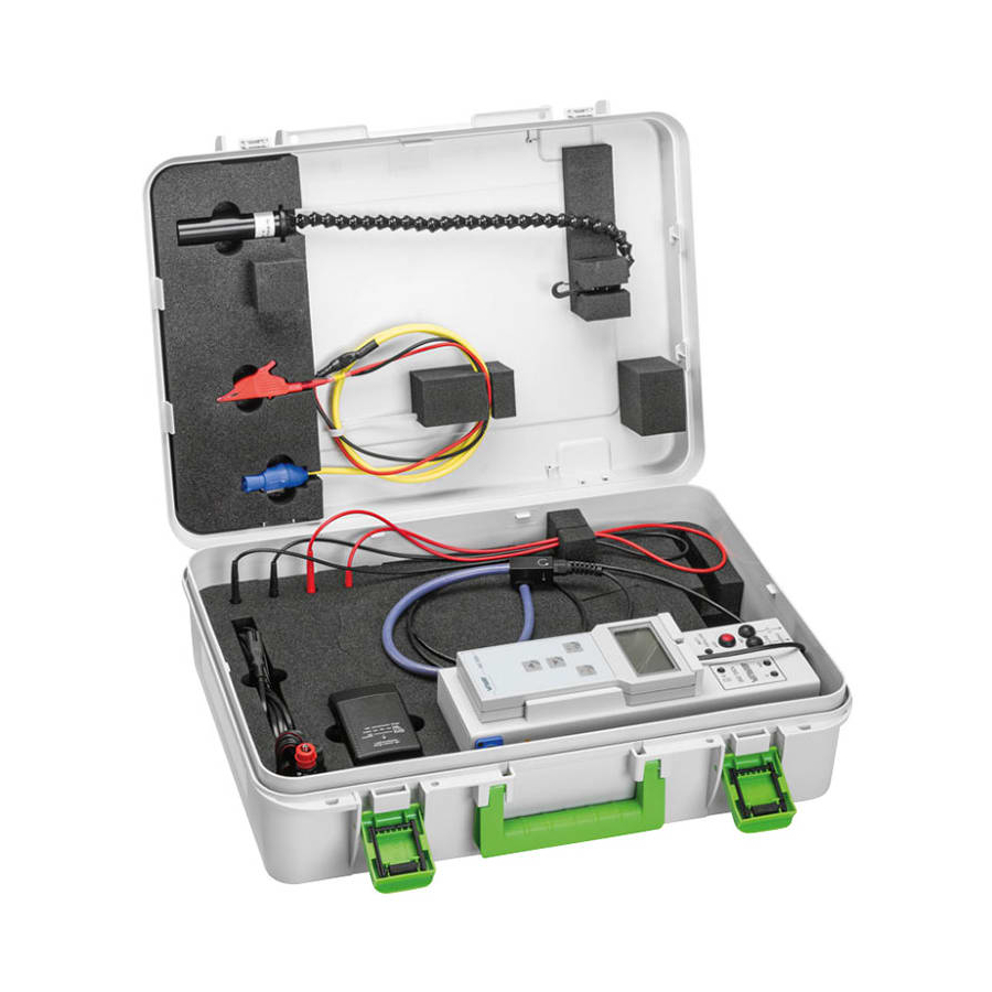
- Page 1 Us er manual Cable identification system K S G 200 A /K S G 200 T A Figure: KSG 200 TA ▪ ▪ B A U R G m b H R a i f f e i s e n s t r . 6 8 3 2 S u l z , A u s t r i a...
- Page 2 BAUR GmbH, 6832 Sulz, Austria. We reserve the right in the interests of our customers to make amendments as a result of further technical development.
-
Page 3: Table Of Contents
Rating plates ................ 21 3.6.2 Safety and information signs on the system ......22 Technical data .................... 23 Operating the system ................25 Cable identification with KSG 200 A ..........25 Switching on and off the system ............26 822-170-3 iii / 60... - Page 4 Table of contents KSG 200 A/KSG 200 TA Display ....................26 5.3.1 Symbols ................26 5.3.2 Infocodes and their meaning ..........28 Standard and expert mode ..............29 Connecting the system ................30 Signal coupling types ................. 30 Setting up the system ................ 30 Checks to perform before commissioning .........
- Page 5 KSG 200 A/KSG 200 TA Table of contents 11.5 Charging battery via the vehicle charge cable ........51 11.6 Check if the charger is damaged ............51 11.7 Testing fuses in safety measurement cables (KSG 200 TA) ..... 52 11.8 Replacing fuses in safety measurement cables (KSG 200 TA) ..53 Faults and corrective measures ...............
-
Page 6: About This Manual
Consider this user manual to be a part of the product and store it in an easily accessible location. If this user manual is lost, please contact BAUR GmbH or your nearest BAUR representative (http://www.baur.eu/baur-worldwide). Application of instructions This user manual applies for cable identification systems with battery: ... -
Page 7: View Settings
KSG 200 A/KSG 200 TA About this manual Danger levels Signal words in the safety instructions specify the danger levels. DANGER Will lead to severe injuries or death. WARNING May lead to severe injuries or death. CAUTION May lead to light to moderate injuries. -
Page 8: For Your Safety
In addition, the user must have: Knowledge of the technical equipment and operation of KSG 200 A/KSG 200 TA Knowledge of plant engineering (cable types, switchboard plant, etc.). -
Page 9: Avoiding Dangers, Taking Safety Measures
KSG 200 A/KSG 200 TA For your safety Avoiding dangers, taking safety measures When installing the test system and operating KSG 200 A/KSG 200 TA observe the following rules and guidelines: Accident prevention and environment protection rules applicable for your country ... -
Page 10: No Operation In Areas With Risk Of Explosion And Fire
Commissioning and operation of KSG 200 A/KSG 200 TA are permitted only in compliance with the EN 50110 (EU/EFTA countries) or with standards applicable in your country. - Page 11 KSG 200 A/KSG 200 TA For your safety Cable identification on de-energised cables Observe 5 safety rules Comply with the following safety rules before beginning tasks in and on the electrical plant: 1. Disconnect the test object. 2. Secure against re-connection.
- Page 12 For your safety KSG 200 A/KSG 200 TA Cable identification on live cables You can carry out cable identification on live cables only with KSG 200 TA. Note that working on live parts and plants can be fundamentally dangerous. When connecting the system to the cable that is to be identified, the operator can come close to live parts during preparation and while performing the cable identification.
- Page 13 The charger is an electrical equipment that feeds voltages and currents that are dangerous for humans. Only use the supplied charger for KSG 200 A/KSG 200 TA. Protect the charger against humidity. Use the charger only in dry spaces.
-
Page 14: Special Personal Protection Equipment
Special personal protection equipment Personal safety equipment based on the risk assessment for the relevant working conditions is part of the KSG 200 A/KSG 200 TA safety concept. Observe the national safety regulations and your company's working and operating instructions. -
Page 15: Product Information
KSG 200 A/KSG 200 TA Product information RODUCT INFORM ATION Device types The cable identification system KSG 200 A is available in two types: KSG 200 A for cable identification on de-energised cables KSG 200 TA for cable identification on live cables (CAT IV/600 V) - Page 16 Product information KSG 200 A/KSG 200 TA Element Function LED Battery LOW Lights up when the battery level is low If the charger is not connected, the transmitter is automatically switched off after 10 to 20 minutes. OFF button Switches off the transmitter ON –...
-
Page 17: Connection Cables
KSG 200 A/KSG 200 TA Product information 3.2.1 Connection cables Element Function Bayonet port Is used to connect the connection cable to the transmitter Red connection clip Is used to connect the transmitter to the cable or phase that is... -
Page 18: Receiver
Product information KSG 200 A/KSG 200 TA Receiver The receiver with the attached flexcoupler is used to record and evaluate the current pulses and to display the measurement results. The flexcoupler is available in 2 sizes: Ø 150 mm ... -
Page 19: Charger
KSG 200 A/KSG 200 TA Product information Charger The supplied plug-in charger is used to charge the NiMH rechargeable battery pack: 10-12 cells, 2.8 - 7.0 Ah. Technical data Output voltage 10.5 – 20 V DC; 1.0 A Rated capacitance 2.8 –... -
Page 20: Power Supply
After it is fully charged, the receiver can be used for approx. 1 hour. 3.5.1 Battery operation The KSG 200 A/KSG 200 TA transmitter is equipped with a NiMH rechargeable battery pack. Technical data Voltage 12 V Battery life 2.5 - 3.5 h... -
Page 21: Markings On The System
In the receiver, the number 150 and 250 specifies the diameter of the flexcoupler. Serial number KSG 200 (T)A Displays whether it pertains to the device variants KSG 200 A or KSG 200 TA Not applicable here Not applicable here... -
Page 22: Safety And Information Signs On The System
Product information KSG 200 A/KSG 200 TA 3.6.2 Safety and information signs on the system Connection cables Element Function Indicates the red connection cable that is connected to the cable that is to be identified Indicates the black connection cable that is connected to the station ground or to the second phase for the signal return line. -
Page 23: Technical Data
KSG 200 A/KSG 200 TA Technical data ECHNICAL DATA Transmitter Pulse voltage 300 V Pulse current Max. 180 A Pulse sequence 15 pulses/min Degree of protection IP40 Voltage-proof up to Max. 400 V, 50/60 Hz Measurement category CAT IV/600 V*... - Page 24 Technical data KSG 200 A/KSG 200 TA Receiver KSG 200 A/KSG 200 TA Sensor Flexcoupler Ø 150 mm or Flexcoupler Ø 250 mm Sensitivity with galvanic impulse coupling: 100 % at a loop resistance of 400 Ohm (I = 0.75 A) with inductive impulse coupling: 100 % at loop resistance of <...
-
Page 25: Operating The System
When all 3 parameters match, it pertains to the desired cable. This is displayed accordingly on the receiver display. Calibration The first step during cable identification with KSG 200 A/KSG 200 TA is the calibration of the transmitter and receiver. During calibration, the connected cable is analysed for faults and amplitude. As the amplitude depends on the loop resistance, the receiver automatically sets the gain to 100% of the output amplitude. -
Page 26: Switching On And Off The System
Operating the system KSG 200 A/KSG 200 TA Switching on and off the system Switch on the system Press the ON / Battery Charger button on the transmitter for approx. Battery operation one second. Operation with supply voltage Connect the transmitter to the supply voltage DC 12 V. - Page 27 KSG 200 A/KSG 200 TA Operating the system Symbol Description Indicates that a branch has been detected: Positive current polarity Signal amplitude between 10% and 64% Indicates that no cable has been located Indicates that this is a wrong cable Displays the signal amplitude ...
-
Page 28: Infocodes And Their Meaning
Contacts on transmitter and/or receiver are dirty. Clean the contacts. KSG 200 A: Disconnect the connection cable from the cable Warning: External voltage at output. that is to be identified. The connected cable is live. -
Page 29: Standard And Expert Mode
The loop resistance has changed. Recalibrate the system. Standard and expert mode KSG 200 A/KSG 200 TA has two operating modes: Standard mode In standard mode, the gain is set automatically after the calibration. No other settings are required. -
Page 30: Connecting The System
Connecting the system KSG 200 A/KSG 200 TA ONNECTING THE SYSTEM Signal coupling types There are two options to couple the current pulse in the cable that is to be identified: galvanic inductive with a clip-on current transformer (optional) The inductively coupled current pulse is essentially weaker than the galvanically coupled pulse. -
Page 31: Important Information On Connecting The Flexcoupler
KSG 200 A/KSG 200 TA Connecting the system Important information on connecting the flexcoupler The direction arrow of the flexcoupler should point towards the far end. Position the flexcoupler closure as far as possible from the adjacent phases. -
Page 32: Connecting The System For Galvanic Signal Coupling
Connecting the system KSG 200 A/KSG 200 TA 6.5.3 Connecting the system for galvanic signal coupling Prerequisite The workplace must be disconnected from the power supply. Further information: chapter Ensure there is no voltage at the work place (on page 31) Connection diagram ... - Page 33 KSG 200 A/KSG 200 TA Connecting the system Return current via the cable screens of adjacent cables (1-phase cable) Special features of the connection: Adjacent phases are earthed. Cable sheath of the cable that is to be identified is disconnected from the earth at the near end.
- Page 34 Connecting the system KSG 200 A/KSG 200 TA Return current via another phase (1-phase cable) Special features of the connection: Return current flows back via a couple of adjacent phases. Influences due to vagrant currents will be avoided by this connection. It is especially helpful during cable identification in paper-insulated cables (PILC).
-
Page 35: Connecting The System To Live Cables (Ksg 200 Ta)
KSG 200 A/KSG 200 TA Connecting the system Sheath-isolated 3-phase cable Special features of the connection: All phases of the cable that is to be identified are earthed and shorted at the far end. Cable sheath of the cable that is to be identified is earthed at the near and far end. -
Page 36: Connecting The System For Galvanic Signal Coupling
Connecting the system KSG 200 A/KSG 200 TA 6.6.2 Connecting the system for galvanic signal coupling Prerequisites Cable identification system KSG 200 TA Measurement category of electric circuit ≤ CAT IV/600 V Connection set to connect to live LV cables (standard delivery) Prepare safety measurement cable 1. -
Page 37: Connecting The System For Inductive Signal Coupling (Optional)
KSG 200 A/KSG 200 TA Connecting the system 1. Leave all consumers connected. 2. Connect the transmitter with the safety measurement cable in such a way that the current flows in the direction of the transformer station. Unlike during signal coupling to disconnected cables, during cable identification on live cables, the flow of the current pulse is determined from the impedance of the connected consumers and feed source (transformer station). -
Page 38: Applying The Flexcoupler With Flexible Rod
Connecting the system KSG 200 A/KSG 200 TA Connection example 1. Place the clip-on current transformer in such a way that the arrow on the current transformer points in the direction of the far end. 2. Place the flexcoupler in such a way that the arrow on the flexcoupler also points in the direction of the far end. -
Page 39: Securing The Test Area
KSG 200 A/KSG 200 TA Connecting the system Securing the test area 1. Secure the work area in compliance with the road traffic regulations in your country. 2. Make sure that except for the tester, no other person is able to access the work area. -
Page 40: Cable Identification
Cable identification KSG 200 A/KSG 200 TA ABLE IDENTIFICATION Calibrating the system and identifying cables Calibration Switch on the transmitter. Leave the receiver in the transmitter holder. The cable identification system is moved to the initial state. The receiver is charged. -
Page 41: Evaluating Measurement Results
KSG 200 A/KSG 200 TA Cable identification Cable identification Place the flexcoupler around the cable that is to be identified or the phase in such a way that the arrow on the flexcoupler points towards the far end. Important: •... -
Page 42: Carrying Out The Measurement In Expert Mode
Cable identification KSG 200 A/KSG 200 TA Display Other steps If possible, couple the current pulse galvanically. To check the measurement result, carry out the measurements on all adjacent cables and phases. The signal polarity on the adjacent cables or phases should be negative. -
Page 43: Activating The Expert Mode
KSG 200 A/KSG 200 TA Cable identification 7.3.1 Activating the expert mode The expert mode can only be activated after calibrating the system. 1. Calibrate the system. Further information: Chapter Calibrating the system and identifying cables (on page 40) (Steps 1 to 6) 2. -
Page 44: Current Measurement
With KSG 200 A/KSG 200 TA, you can measure current (50/60 Hz) up to 199 A on the connected cable. 1. To measure the current on the cable that is to be identified after calibration, press the button. -
Page 45: Phase Determination (Optional)
Phase determination (optional) HASE DETERMINATION OPTIONAL The phase determination with KSG 200 A/KSG 200 TA works similar to the cable identification. On the earthed and shorted substation, current pulses are coupled to the phases L1, L2, L3 detected there with the clip-on current transformer AZ (optional). At the place of installation, the receiver is connected to the specific phases one after the other. - Page 46 Phase determination (optional) KSG 200 A/KSG 200 TA 3. Perform the measurement. Proceed in exactly the same way as during cable identification. If the detected current pulse shows the positive polarity and the corresponding signal amplitude, the respective phase is detected.
-
Page 47: Completing The Cable Identification
KSG 200 A/KSG 200 TA Completing the cable identification OMPLETING THE CABLE IDENTIFICATION 10.1 Safety instructions Cable identification on de-energised cables DANGER Dangerous voltage in test object. Danger to life or risk of injury due to electric shock. Before touching the test object, discharge, earth and short it: at the connection point and at the far end. -
Page 48: Dismantling The Test Structure
Completing the cable identification KSG 200 A/KSG 200 TA 10.2 Dismantling the test structure 1. Remove the flexcoupler from the cable or phase. 2. Switch off the transmitter with the OFF button. 3. Place the receiver in the transmitter holder. -
Page 49: Maintenance
KSG 200 A/KSG 200 TA Maintenance AINTENANCE 11.1 Safety instructions NOTICE Damage to devices due to improper handling The user is liable for any damage caused due to improper maintenance or care. Never take apart the system and installed components. This can damage the device. -
Page 50: Charging The Transmitter Battery
The charger is an electrical equipment that feeds voltages and currents that are dangerous for humans. Only use the supplied charger for KSG 200 A/KSG 200 TA. Protect the charger against humidity. Use the charger only in dry spaces. -
Page 51: Charging Battery Via The Vehicle Charge Cable
KSG 200 A/KSG 200 TA Maintenance 11.5 Charging battery via the vehicle charge cable The 12 V connection on the transmitter is designed only for charging the battery fully. However, if you are unable to connect the charger at the place of use, you can charge the empty battery partially via the car battery onboard power outlet and complete the measurement. -
Page 52: Testing Fuses In Safety Measurement Cables (Ksg 200 Ta)
Maintenance KSG 200 A/KSG 200 TA 11.7 Testing fuses in safety measurement cables (KSG 200 TA) Prerequisites Multimeter Fuse: F 7 A, 50 kA @ AC 600 V Procedure Unscrew the fuse holder from the safety measurement cable Remove the fuse from the fuse holder. -
Page 53: Replacing Fuses In Safety Measurement Cables (Ksg 200 Ta)
KSG 200 A/KSG 200 TA Maintenance 11.8 Replacing fuses in safety measurement cables (KSG 200 TA) Prerequisites Fuse: F 7 A, 50 kA @ AC 600 V Procedure Unscrew the fuse holder from the safety measurement cable Remove the faulty fuse from the fuse holder. -
Page 54: Faults And Corrective Measures
5. If the fault occurs again, contact your BAUR representative (http://www.baur.eu/baur-worldwide). It may be possible for the BAUR GmbH After Sales Service Team to determine the cause of the fault remotely. To do so, please specify the following data: ... -
Page 55: Transportation And Storage
KSG 200 A/KSG 200 TA Transportation and storage RANSPORTATION AND STORAGE 13.1 Transporting the system Observe the following during transportation or dispatch: NOTICE! Damage to system due to improper transportation. During transportation, comply with the ambient conditions specified in the technical data of the system. -
Page 56: Warranty And After Sales
15.2 Disposing of rechargeable battery pack and charger The KSG 200 A and KSG 200 TA transmitters are equipped with a NiMH rechargeable battery pack. The NiMH rechargeable battery pack and the charger must not be disposed of in the domestic waste, rather must be disposed of as hazardous waste. -
Page 57: Delivery Scope And Options
Delivery scope and options ELIVERY SCOPE AND OPTIONS KSG 200 A KSG 200 TA KSG 200 A transmitter with integrated KSG 200 TA transmitter with integrated rechargeable battery rechargeable battery KSG 200 pulse receiver with flexcoupler (variants... -
Page 58: Index
Deactivating the expert mode • 43 Cable identification on live cables • 12 Delivery scope and options • 57 Cable identification with KSG 200 A • 25 Device types • 15 Calibrating the system and identifying cables • Dismantling the test structure • 48 Display •... - Page 59 KSG 200 A/KSG 200 TA Index Information on the screenshots and graphics Storing the system • 55 used • 7 Structure of safety instructions • 6 Instructions to the user • 8 Switching on and off the system • 26 Intended use •...
- Page 60 822-170-3 BAUR GmbH Raiffeisenstraße 8 6832 Sulz / Austria headoffice@baur.at www.baur.eu 822-170-3-phd-05.10.2016...
Need help?
Do you have a question about the KSG 200 TA and is the answer not in the manual?
Questions and answers