Sign In
Upload
Download
Table of Contents
Contents
Add to my manuals
Delete from my manuals
Share
URL of this page:
HTML Link:
Bookmark this page
Add
Manual will be automatically added to "My Manuals"
Print this page
×
Bookmark added
×
Added to my manuals
Manuals
Brands
Carel Manuals
Controller
IRDR Series
User manual
Carel IRDR Series User Manual
Universal infrared controllers
Hide thumbs
1
Table Of Contents
2
3
4
5
6
7
8
9
10
11
12
13
14
15
16
17
18
19
20
21
22
23
24
25
26
27
28
29
30
31
32
33
34
35
36
37
38
39
40
41
42
43
44
45
46
47
48
49
50
51
52
53
54
55
56
57
58
59
60
61
62
63
64
65
66
67
68
69
70
71
72
73
74
75
76
77
78
79
80
81
82
page
of
82
Go
/
82
Contents
Table of Contents
Bookmarks
Table of Contents
Italian
Table of Contents
Introduzione
Caratteristiche Principali
Descrizione del Frontale Degli Strumenti
Utilizzo Degli Strumenti Della Serie Infrared Universale
Installazione
Configurazione DI Fabbrica
Modi DI Funzionamento
Programmazione
Accesso da Tastiera
Modifica del Set-Point (St1)
Modifica del Secondo Set-Point (St2)
Parametri "C" Per Termocoppie, Sonde in Tensione E in Corrente
Come Modificare Il Modo (Parametro C0)
Accesso da Telecomando
Modifica Parametri da Telecomando
Stato Della Regolazione Durante la Modifica Dei Parametri
Validità Della Modifica Parametri
Reset del Controllo
Sistemi Avanzati DI Programmazione E Supervisione
Descrizione Dei Parametri
St1 Set-Point Principale
St2 Set-Point Secondario
C0 Modo DI Funzionamento
P1 Differenziale DI St1
P2 Differenziale DI St2
P3 Differenziale Zona Neutra
C4 Autorità
C5 P O P+I
C6 Ritardo Degli Inserimenti DI Uscite Differenti
C7 Tempo Minimo Tra Due Accensioni Successive
C8 Tempo Minimo DI Spegnimento
C9 Tempo Minimo DI Attivazione
C10 Ritardo Delle Uscite in Caso DI Allarme Sonda (Er0)
C11 Rotazioni
C12 Tempo DI Ciclo PWM
C13 Tipo DI Sonda
P14 Calibrazione
C15 Valore Minimo Per Ingressi in Corrente E Tensione
C16 Valore Massimo Per Ingressi in Corrente E Tensione
C17 Filtro Sonda
C18 Unità DI Misura Per Temperatura: "C" O "F
C19 Seconda Sonda NTC
Funzionamento Differenziale C19=1
Compensazione C19=2, 3 O 4
C21 Valore Minimo Ammesso da ST1
C22 Valore Massimo Ammesso da St1
C23 Valore Minimo Ammesso da ST2
C24 Valore Massimo Ammesso da St2
P25 SET Allarme DI "Bassa
P26 SET Allarme DI ALTA
P27 Differenziale ALLARME: Reset
P28 Ritardo Attivazione Allarme
C29 Gestione Ingresso Digitale 1
C29=3 Allarme Esterno Ritardato (Ritardo=P28)
C29=4 On/Off
C30 Gestione Ingresso Digitale 2
C31 Stato Uscite con Allarme da Ingresso Digitale
C32 Indirizzo Seriale
C33 Funzionamento "Speciale
C50 Abilitazione Tastiera E/O Telecomando
C51 Telecomando: Codice Abilitazione
Descrizione Funzionamento Speciale
Descrizione DIPENDENZA
Funzionamento TIMER
Descrizione INSERZIONE
Descrizione DIFFERENZIALE/LOGICA
Note Integrative al Funzionamento Speciale
Suggerimenti Per Scegliere Il Modo DI Partenza
Esempi DI Utilizzo del Funzionamento Speciale
Lista Completa Dei Parametri
Ricerca E Eliminazione Dei Guasti (Strumento E Telecomando)
Condizioni DI Allarme, Cause E Rimedi
Moduli Opzionali
Modulo Uscita Analogica
Modulo ON/OFF
Modulo Alimentatore/Convertitore
Caratteristiche Tecniche Dei Modelli Serie Infrared Universale
Caratteristiche Tecniche del Telecomando
Schemi DI Collegamento
Versioni IR32 NTC
Versioni IR32 Non NTC
Versioni IRDR NTC E Non NTC
Connessione Sonde
Glossario
Tabella Codici Dei Modelli Serie Infrared Universale
Dimensioni
English
Introduction to the IR Series
Main Features
C29, Digital Input no
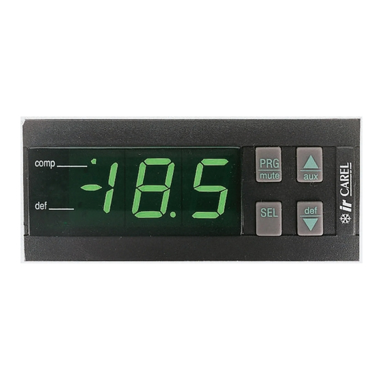
Front Panel
C30, Digital Input no
Use of Universal Infrared Instruments
How to Install the Controller
Easy Set-Up: Factory-Set Configuration
Advanced Set-Up: Different Modes of Operation
Modifica Dei Parametri DI Tipo "P
Programming the IR Controller
Access Via Keypad
Set-Point Modification (St1)
Second Set-Point Modification (St2)
Modification of 'P' Parameters
Modifica Dei Parametri DI Tipo "C
Modification of 'C' Parameters
Programming the Controller Via Remote Control
How to Modify Parameters Via Remote Control
Confirming the Newly Set Values
Reset of the Control
Advanced Programming Tools and Supervisory Systems
Description of the Parameters
St1, Main Set-Point
St2, Second Set-Point
C0 Mode of Operating
P3, Dead Zone
C4, Authority
C5, P or P+I
C6, Time-Delay before Energizations of Different Outputs
C7, Minimum Time-Interval between Succ. Energizations
C8, Minimum Disenergization Time-Interval
C9, Minimum Energization Time-Interval
C10, Time-Delay before Sensor Alarm (Er0)
C11, Rotations
C12, PWM Cycle Time
C13, Type of Sensor
P14, Calibration
C15, Min. Value of Voltage and Current Inputs
C16, Max. Value of Voltage and Current Inputs
C17, Sensor Response
C18, Temperature Unit of Measure °C/°F
C19, Second NTC Sensor
C19=1, Differential
C19=2,3,4, Offse
C21, Lower St1 Threshold
C22, Higher St1 Threshold
C23, Lower St2 Threshold
C24, Higher St2 Threshold
P25, Low Temperature Set-Point
P26, High Temperature Set-Point
P27, Alarm Differential: Reset
P28, Time-Delay before Alarm Activation
C29=3 Delayed External Alarm with Manual Resert (P28)
C31, Output Status in the Event of Alarm Via Digital Input
C32, Serial Address
C33, Special Mode of Operation
C50, Operating Keypad And/Or Remote Control
C51, Remote Control: Access Code
Special Mode of Operation
Dependence
Timer
Further Information on the Special Mode of Operation
Hints for Choosing the Right Mode
Advanced Set-Up: List of the Parameters
Alarm Conditions, Causes and Remedies
Optional Modules
Analogue Output Module - Code CONV0/10A0
ON/OFF Module (Code CONV0N0FF0)
Technical Specifications of the Remote Control
Wiring Diagrams
IR32 with NTC Input
IR32 with Pt100, J/K Tc or V/I Input
IRDR Versions
Sensor Connection Diagrams
Glossary
Codes of the Universal Infrared Models
Dimensions
Advertisement
Quick Links
1
Programmazione
2
Alarm Conditions, Causes and Remedies
Download this manual
Serie Infrared Universale / Universal Infrared Series
Manuale d'uso
User manual
Technology & Evolution
Table of
Contents
Previous
Page
Next
Page
1
2
3
4
5
Advertisement
Table of Contents
Need help?
Do you have a question about the IRDR Series and is the answer not in the manual?
Ask a question
Questions and answers
Subscribe to Our Youtube Channel
Related Manuals for Carel IRDR Series
Controller Carel IR32M Manual
(63 pages)
Controller Carel DN33 Universale Series Replacement Instruction
(2 pages)
Controller Carel DN33 Universale Quick Start Manual
(2 pages)
Controller Carel IR33 Application Manual
Universal controllers (41 pages)
Controller CAREL ir33 Handbook
Controller for cooling equipment (12 pages)
Controller Carel ir33+ small wide User Manual
Electronic controller (56 pages)
Controller Carel IR33+ Programming Instructions Manual
(13 pages)
Controller Carel ir33+ User Manual
(60 pages)
Controller Carel IRMPX00000 User Manual
Mpx series (60 pages)
Controller Carel IRMPX10000 User Manual
Mpx series (60 pages)
Controller Carel IRMPXMM000 User Manual
Mpx series (60 pages)
Controller Carel ir33 Universale series User Manual
Universale electronic controller (48 pages)
Controller Carel IR33V7HR20 User Manual
Electronic control (55 pages)
Controller Carel IR Series User Manual
Universal infrared (83 pages)
Controller CAREL IR32 Series User Manual
Universal infrared controllers (82 pages)
Controller Carel ir33+ FMC Quick Manual
Solution for embraco fullmotion compressor (64 pages)
Table of Contents
Save PDF
Print
Rename the bookmark
Delete bookmark?
Delete from my manuals?
Login
Sign In
OR
Sign in with Facebook
Sign in with Google
Upload manual
Upload from disk
Upload from URL


Need help?
Do you have a question about the IRDR Series and is the answer not in the manual?
Questions and answers